Injection Mould Construction

A molding according to the function of each of its parts can be divided into four sections 1. Introductory part of the plastic nozzle into the cavity cavity 2. penunjuang system (support system) 3. demolding system 4. heat transfer system

Mold Base Standard Part

In the manufacture of injection mold, mold base is an integral part, mold maker can make your own mold base or buy a standard mold base, the system of the mold base can be adjusted with the construction standards required, both for the two plate and three plate, stripper plate ejectors, hot runner and mold base for a screw, when the entire standard mold base is not there to meet the new final step is to make a special mold base.

Injection Mould Classification

classification or types of mold injection very depend on what we need to make the plastic parts, because every parts have specific and unique design. when design molds we must see what the influencing factor like geometry, number of cavities, ejection principle, plastic material and shape of part.

Injection Mold Cooling

This section is the most important part of the overall mold cylcle time, because in one cycle time, the process of heat exchange to spend about 70-80% of the total cycle time, thus setting the optimal heat transfer system will greatly affect the quality and cycle time of a product.

Undercut System : Cam, Angular, Lift Cavity, Loose core

cavity and core, and its derivatives when there are undercut on product, design and construction of a good core cavity and in accordance with the requirement could increase the life of tooling itself, reduce material consumption, reduce dependence on maintenance inserts, and can reduce the cost of making the mold so the mold cost per products also declined.

Showing posts with label Mold Construction. Show all posts

Monday, March 7, 2011

Lifting bolts hole design in injection mold

Plate transfer process occurs during the machining and assembly of mold, both for the cavity and mold base plate, especially for the plate with a weight greater than 20 kg, threaded hole necessary to facilitate the transfer process. cause may be in a mold plate having a various of machining processes with different types of machines. Base on position of hole the type of lifting bolts can divided became two, perpendicular to face, and parallel with face of plate.
perpendicular to face
beside transfer process, lifting bolts also important for lift out cavity insert from mold base, flat wide plate usually use magnet to lift from one machine to another machine or station, but if shape of plate doesn’t flat it need bolts hole to attach eye bolts, then use crane that connected to eye bolts for lifting the mold base plate or cavity plate.


Parallel with mold face.
Especially for mold base, this hole must available because transfer mold base usually use eye bolt that connected to crane, for mold base plate that use horizontal machining also use this hole to connected with crane, picture below shown mold base with metric bolt hole and eye bolts ready for transfer with crane


Wednesday, December 22, 2010

using mold base become locking block of slider unit

moldbase sometimes can be used for the locking block on the slider unit, this is basedon several reasons, for example, to reduce cost, by reducing the insert locking block, the other reason is required surface area for the locking block.


illustration picture above shows the angular pins are bolted to the mold base and the mold base made pocket instead of locking block,

to keep the process easy to do maintenance, should be installed oil slide plate, so when it can wear easily replaced without the need to change their plate slider block.
This model is widely used for large parts and molds with a tonnage greater than 350 tons, other advantage is the size of the mold base to be more compact and small, so the cost for the mold base can also be reduced, and if the size is smaller base can mold into tonnase also smaller

Sunday, November 21, 2010

Loose core for ejecting undercut at injection mold


Picture above shows the loose core, or often also called slope ejectors or inclined pin, loose cores is one method to overcome the undercut on the product, particularly undercut the core position facing into the bottom (towards the sprue bush-center of mold) that undercut it can not be made simply by using slider method, part of the loose core complete with mold base include:

1. Top clamping Plate
2. stripper plate
3. cavity plate
4. core plate
6. support plate
7. top ejector plate
8. bottom ejector plate
9. bottom clamping plate
10. loose core rod
11. loose slide unit
12. bushing

for more details look at the picture below, which shows the current position of loose cores prior to the occurrence of loose core ejecting position after ejecting process, shortly after the mold is closed and the injection process, loose cores in the closed position (note the closed mold), after the injection process is complete done, at the push of ejector rod, ejector plate both upper and lower parts helped push out through the ejector, while the loose-core because it has a certain slope (generally 8-15) when driven will move slowly into center with the aid of friction on inclined leader pin bushings, so the position Loose cores are separated from the undercut product (mold opened)

Slide the unit mounted on the ejector plate is always on the top or at the bottom, and the main mover of the loose core are ejector rod simultaneously with the process of ejecting, points to consider in designing the loose core is strokes and angles used, too little angle of it can reduce the occurrence of abrasion (wear) but required a long stroke.
If angle is too large can cause the inclined pin (loose core) broken because of the occurrence of high abrasion, but required a shorter stroke. The angle that is used is usually between 8-15 0, while the stroke must be exceeded 5 mm or more to keep the loose core is certain regardless of the undercut in the product.

Friday, November 12, 2010

Loose cavity inner undercut release method in injection Molding

one way to release the undercut is to loose cavity, the opposite of loose cores, loose inner cavity is used to remove the undercut in the cavity area, note the image below for more details,

1 = top plate
2 = runner stripper plate
3 = cavity plate
4 = core plate
5 = locking block for loose cavity
6 = angular pin for loose cavity system
7 = loose insert cavity


some designers also say that with the inner mold cavity slider, whatever his name is, in essence, functions and works the same way. when the first opening between the top runner stripper plate (2) with the cavity plate (3) top plate will pull locking block (5) together with the angular pin (6), aided by the spring on the insert cavity, this movement causes the loose insert cavity to move straight straight to the angular movement of the pin, as a result of friction between the angular pin with a hole in the loose insert cavity.

when construction is used, ie if your product has undercut formation on a position in the cavity region, angular corners and locking block commonly used ranged from 8 to 20 degrees, above the angle can cause angular cartilage pin was broken, because the force that fought too large.
Another thing to note is the stroke, you must ensure that the stroke of movement of loose cores must be secure, which is about the length undercut products coupled with the 5-10 mm.

Monday, August 2, 2010

Locking Block With Angular Slider

What should you do when the slider design and found that the angular slider too long? There are many ways to change the design so that the angular length of the slider pins are still reasonable when compared to its diameter.in design between the angular diameter and length of the slider pins should be noted, the length of angular slider pins that are too long can lead to easily broken when the mass production run, especially if the small angular diameter, the way the installation is also a concern to be easy in the process of repair when damage occurs.
the above  picture, I took when designing the angular pin slider, when the client wants the angular pin slider must exist, and based on the calculation of stroke, it turns out the angular pin length is too long, surely this is dangerous and i should change the design concept.
other than dangerous, the above design concept is also difficult in maintenance because if the angular pin broke the mold base must be dropped from the injection machine, disassembly the mold then can be replaced, this is because the angular pin must be in pairs from the top plate embedded in the cavity

Locking Block With Angular Slider
This design concept in addition to saving space, saving the long angular slider also has the advantage of easy installation and maintenance, although the angular pin mold was broken when used for production, the mold does not need to send down from the injection machine to replace it. look at picture below


on the design concept above, I only use one bolt to tighten to the cavity plate, simple but I'm sure I could save the angular length of approximately half of the angular slider before. The above concept also facilitates the repair process.


The second alternative was similar, but the difference is the number of bolts are used and how big a part of the locking block affixed to the cavity plate, the first altenative collar only are plugged into the cavity plate, and the bolts, of course, only part that holds the slider in the section just the collar. A second alternative is different from all bagianya embedded in the plate cavity.
I chose the second alternative concept, the concept was made 3D and 2D drafting calculations based on a stroke, for details, under the following 3D image is the result of the 3D design of the second alternative.


Saturday, June 26, 2010

slider construction : cam or angular pin

posts related to construction and part-bagianya slider has been my post, about the cooling on the slider, the basic construction for the slider, the slider and the main part, please see previous post to learn the basic construction and when we should use the slider, This post will discuss about when we need to use of the slider that use angular pin or just cam slider, what advantages and disadvantages of both types of construction such slider. 
ANGULAR PIN
basically, the type of construction of the slider based on how to pull out the core slider is divided into three types, first use the angular pin,using the force of the angular pin at a certain angle, the slider block would be pull out, the second is a cam slider, just use the thrust of the spring and stopper on the slider, and calculating a stroke, cam slider allows you to easily pull the slider core, the third is the use of hydraulic or pneumatic system to pull the slider core, specifically for the third way is needed so that movements of individual controls in accordance when the slider open mold and mold close.picture below shows slider with angular pin system.


 picture above shown standard complete construction for slider, it's include cooling plug, stopper (blue color), adjustment plate between locking block and slider core(blue), guide rel (pink) etc. angular pin system very common use in slider system, Angular sometimes do not have a round pin, shape the box is also commonly used, actually used the same angle, both will be used by considering the strength, structure, mold, and the available space.
The advantage is the use of angular pins can be used for parts that have undercut short or long, easy to maintain when the angular broken, just enough to change the angular pin. inexpensive in manufacture, and can be used for long-stroke slider to medium, the angular pin length has not touched bottom plate. 


for instance,look at picture above if undercut wide for most of the parts, use the slider two pins with a diameter sufficient, then you will get a strong slider construction and safe.

CAM SLIDER
while the slider does not require angular cam pin, the cam slider there are several types of commonly used, the clamp type,  two angle type, cam units type and one direction cam. because in using the cam to take calculation of a stroke is used, why?? it's to prevent slider core not be separated from the locking block, and the strength of the spring, so that true core slider can move and hit the stopper. cam slider can only be used for minor stroke (0.5 mm-5mm), small undercut, and not too wide undercut form.

a benefit is a cam slider can be used for high cycle time, mold construction, saving space, and easy assembly.

whereas the less than the limited form that can be undercut in the form, was difficult in the manufacture and maintenance. 


Wednesday, May 6, 2009

Sleeve ejector system

This system use when part have tolerance or good dimension so, so we can’t put ejector in those face, or ejector prohibited in that face other reason is part have hole and face that can touch with ejector is very small and surrounding the hole. Look at picture below


Red face indicated that ejector is prohibited, for that reason the only way to eject those part is using sleeve ejector that will located at green face (look at picture)

Basic construction of sleeve ejector system is like picture below


How Sleeve Ejector Works

Basic mechanism of sleeve ejector is how to make insert pin doesn’t move when sleeve ejector move to eject the product.


Picture above shown step by step when sleeve ejector moving to eject part, the main part on those picture are product (yellow) sleeve ejector (green), core insert pin (white at center of sleeve ejector) mold base core (light blue at side sleeve core), cavity insert (dark blue), cavity pin insert (pink at center of dark blue), and cavity mold base (light blue surrounding cavity insert pin.

A.     After plastic material injected at cavity insert then cooling water/liquid will flow to transfer heat from mold to liquid. At this position mold base still close, just seconds before ejecting process begin.

B.     Ejecting process begin, first mold will open, core insert include cavity insert will move to backward, because shrinkage of material always move to inner side, product will stick in core insert pin.

C.     Sleeve core move forward when ejecting process begin, sleeve core will eject the product, and the product will leave core insert pin, because core insert pin doesn’t move forward.

After sleeve core move same as ejector stroke, product will drop, and.. Gotcha.. you get the product.

Saturday, October 11, 2008

Ejector Component List for ejector pin type

Each type of mold have their own ejector system characteristics, such as : one step ejector, two step ejector, stripper ejector system, pin and blade ejector system, gas ejector, and vacum ejector. from various ejector system that available all of that type have main part or main component. picture below shown common and main component for ejector system. this image size about 700X500 px, click the picture to enlarge.


picture above shown side view of ejector system, the target is to eject the product (black) from core insert after mold open. when the ejector system work and push the product to outer parting line the side view picture is like below


Ejector working system
with above system, how could the ejector push the product? below i will try to explain step by step
1. after cavity of mold injected with plastic material, and cooled moldbase will open, and product have to eject from the core insert.see the open condition of molds.
2. after mold base in open condition like picture below

rod from injection machine will push the ejector rod,because ejector rod connected to ejector plate, ejector plate will move forward.
3. ejector guide pin will guide those moving, to prevent scratch and guide the moving more easily use ejector guide bush, ejector pin and ejector guide bush will have little friction.
4. ejector pin clamped between two ejector plate, because that ejector pin will also move forward push the product.
5. after product take it out from cavity, mold base will moving close again.
6. and because at the return pin have spring, spring and closing mold will guide ejector back to the position (1)

Ejector Component List
this list is standard minimum to make ejector system
1. Ejector plate, place for ejector and ejector guide bush, shoulder bolts and return pin.
2. Ejector Backing Plate, place for clamping the ejector and push back the ejector.
3. return pin, push the ejector plate and ejector backing plate to first position.
4. spring in return pin, to make sure and holds the ejector plate so it's always in back position, when in assembling process, it can lift up the ejector pin, and ejector plate so the position always in back, give the little preloads to ejector plate to make sure the ejector plate position.
5. shoulder bolts, first time lock in assembling molds
6. ejector pin, eject and push the product from core.
7. ejector guide pin, guide the moving of ejector plate.
8. ejector guide pin bush, to make sliding and prevent large contact when moving.
9. support pillar, to prevent large deflection of core plate when injecting the plastic material process held.
10. ejector rod, contact with rod in injection machine, this also passing force from injection machine to ejector plate.
11. ejector bolts, to tie up between ejector plate and ejector backing plate.

Saturday, August 16, 2008

Opening Construction of 3 Plate Mold Type

previous post http://mould-technology.blogspot.com/2008/08/main-construction-pin-at-3plate-mold.html
we can see closed condition of three plate molds

picture below is shown three plate condition when open


basically there are three opening type in 3 plate molds base
1. Sprue Cut Opening
2. Runner Opening
3. Product Opening

below i try to explain in simple words
1. sprue cut opening
this opening will cut sprue from nozzle, so the feeding runner can take easily by arm robot or manually by hand, this opening use puller bolt and runner stripper plate to cut the sprue. the stripper plate will move after puller bolts pulled by cavity plate, remember that puller bolts also end mounted in cavity plate.
the opening length between 5mm until 10mm.
2. runner opening
this opening use tho open runner system, than runner will take by robot or manually,this opening will make space between stripper plate and cavity plate.
to make sure this runner opening safely, attach spring in puller bolts between stripper plate and cavity plate, or use other methods like attach spring in out of puller bolts. length of this opening is same with runner length + 20 mm.

3. product opening, as we know this opening is to open the product, make space so the product can be ejected from core.
this opening length is about length the product + length robot arm + 10 until 20 mm to make save space when product ejected.

Opening Sequence


actually to pull the cavity plate, so the cavity plate can pull the puller bolts than open the stripper plate have two types, using tension link and magnet.
OK, at this post let's learn when using tension link.
1. first Opening is Runner Opening
why ? becouse between stripper plate and cavity plate,some springs always attached at there, some mold designer attach at puller bolts, and the other attach in each side using pin and make some hole to attach the spring. but i prefer attach the spring in puller bolts, it more easy in process.(sorry at picture above i don't write some spring)
2. Second Opening is Product Opening
Parting Line between core - cavity plate always easy to open, when moving plate at the injection machine pull the bottom plate until core plate, it will make Product Opening open.
3. Sprue Cutting Opening
after moving plate pull the core plate, with tension link core plate will pull the cavity plate until cavity plate pull the puller bolt, and make some space to cut the sprue from nozzle.

Wednesday, June 25, 2008

Other Joint Construction Betwen Cooling in cavity and Mold base with O Ring

What is O ring
o-ring is a loop of elastomer with a round (o-shaped) cross-section used as a mechanical seal or gasket. They are designed to be seated in a groove and compressed during assembly between two or more parts, creating a seal at the interface. (wikipedia.com)
O-Rings are torus-shaped (i.e. doughnut-shaped) objects made from elastomeric compounds such as natural or synthetic rubber, and are used to seal mechanical parts against fluid movement (air or liquid). O-Rings perform their sealing action by deforming to take the shape of their cavity, after being oversized to guarantee an predetermined interference fit.( efunda.com)


O ring typically used in one of two seal designs, axial or radial, in mold design to attaching cavity to mold base axial, face type are commonly used then radial type, because axial type is more easy to assembly in mold than radial type.
2D O ring drawing like picture below


Static seals exist where there is no relative motion between the mating surfaces being sealed.


at previous post about basic construction for joining cooling system in cavity and mold base , we can learn how to joint pipe from mold base of mold to cavity site.

various construction can be develop from basic construction, previous post basic construction is fast and cheap construction model, but it isn't good when you in large mold and mass production mold, why? becouse production mold must have endurance until 1000 000 shot.

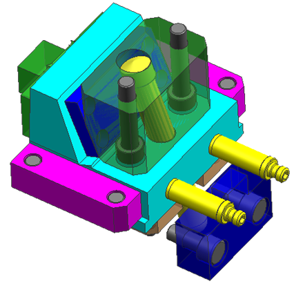
Picture below shown develop construction of joining cooling pipe


blue color indicate mold base side and yellow color indicate cavity side.
basic rule from those picture are :
1. T is height of O ring
2. part of O ring that will receive pressure form cavity plate. 15-30% from it's height is best. this little pressure give to prevent leak when water flow in cooling system.
3. t2 value is same with t, but t2 is horizontal, becouse O ring always made from elastomer plastic, by little pressure we can add O ring to O ring hole.
4. L is Gap between cooling channel and O ring hole.

O-Ring Design Considerations
1. Proper Squeeze
•Compression expressed as a percentage of the free-state cross-sectional thickness:


•Face Seal: 20-30%
•Static Male/Female: 18-25%
•Reciprocating: 10-20%
•Rotary: 0-10%
2. In static seals, where the O-Ring is not in axial motion in the bore, the recommended maximum compression is approximately 40%.
3. The O-Ring must be compressed by a predetermined amount, and this compression determines the O-Ring cross-section diameter.
4. The O-Ring inner diameter is typically chosen to be close to the groove's inner diameter; by selecting it to be slightly less than the groove's inner diameter, the O-Ring will stretch and hug the groove.
5. The Groove Width must be larger than the O-Ring cross-section diameter, to accommodate the radial expansion of the O-Ring when it's axially compressed in the gland.
6. stretch,
- Excessive stretch can overstress material, thin cross section, and reduces % squeeze
- % cross section reduction due to stretch about half of the % ID stretch
7. Sharp Corners, make R in cornet to prevent damage during seal installation.
8. Pressure and Clearance Gap.
Most elastomeric seals are designed to operate within ambient pressure to about 1,500 psi. At very high pressures, the seal must have sufficient strength to resist extrusion into the clearance gap. The chart at right illustrates the recommended limits of the combination of clearance gap (diametral), seal hardness, and pressure differential. picture below shown graph between clearance gap and pressure


9. When it is said that an elastomer is good for an application it is meant that some compounds which include that material are acceptable. Not All. For instance, some compounds of EP are good for brake fluid applications, but most are not acceptable.
10. DO NOT use a lubricant composed of the same material as the O-ring. For example, a silicone lubricant should NOT be used with a silicone O-ring.
11. Avoid using graphite-loaded compounds with stainless steel, as they tend to pit the stainless steel surface over time.

useful reference
http://www.rlhudson.com/O-Ring%20Book/designing-static.html
http://www.pspglobal.com/application-limits/04-watery-substances.html
http://en.wikipedia.org/wiki/O-ring
http://www.efunda.com/DesignStandards/oring/design_guidelines.cfm#axial
http://www.marcorubber.com
http://www.allorings.com/gland_static_axial.htm

Sunday, June 22, 2008

Construction of Cavity Cooling and Mold Base Cooling, O ring

here the basic construction of joining cavity cooling and mold base cooling, we can use from simple construction to joint cavity and mold base cooling with one O ring, or we can use more complex construction like using special plate, and various O ring seal type. here is basic construction to joint the cavity cooling and mold base cooling.


both circular type and straight type cooling can be joint use those construction,
those construction use in half circular type of cooling system like picture below


click the image to see more large

simple joint just need one O ring or rubber seal, O ring pocket is preferred make in horizontal face from assembly, becouse it's make assembly and machining process mold more easily,
basic rule and tolerance to prevent leak in O ring are like picture below


at the cross section of cavity and mold base cooling construction, blue color indicate mold base part, and light yellow indicate cavity block, green is indicate hole or pipe of cooling. light black is O ring before penetrate with cavity block.
however is the simplest construction to join cooling cavity and mold base.

Tuesday, June 17, 2008

Straight Type Cooling for Cavity

Basically cavity system cooling can divide into two type
1. straight type
2. Circular type

straight type system, usually have in and out of water pipe in not same side of mold or cavity. look at picture below

although the pipe that cool of insert part doesn't straight, but if inlet and outlet cooling fluid is not in same side we can consider that those type of cooling is straight. red color pipe indicate inlet and blue color pipe indicate outlet.

second picture below is still same with previous but this picture include the cavity block


yellow part at each side is plug to prevent unwanted flow of cooling, pink block at the center is core insert part. with attach to core block using bolt. Block with blue color is core block before inserted to mold base.

Monday, November 12, 2007

Mold Handling Picture after Assembly

Picture below show 3 plate mold after assembly, the position indicate ready to handling by crane, eye bolt was attached at center of mold plate.

after assembly process, make sure you has attached the tension link in 3 plate mold type or safety bolt or magnet in 2 plate type of mold this to prevent mold plate falling down when handling up with crane, when design eye bolt for handling, give bolt hole about 1 cm more to cavity direction from center line of mass of mold, it's commonly in plate 3 or 4 depending on how wide each mold plate, why it's must move about 1 cm ? the reason is same as safety bold, by move those bolt position when handling with crane mold base will decline about 5-30 degree, and top plate in upper position, this method make more secure when handling.

at this picture below, number 1 is eye bolt position in ready position to handling, and tension link (2) was attached.


from where we know that those mold is three plate, from the characteristics of three PLATE MOLD we can see from picture that :
1. Attached tension link, tension link function is o pull plate number 3 or cavity plate then by puller bolt, cavity plate will also pull the second plate, and cut the runner from nozzle.
2. second plate, it's indicate that those mold is 3 plate mold type, why because in 2 plate type, second plate is doesn't use. second plate is necessary when gate type is pin point gate.
3. runner plate, if you see more carefully, between second plate and third plate attached runner plate, in 2 plate mold type, runner plate does not use, because runner attached in third plate.

green arrow show injection nozzle machine where must be attached and indicate flow of plastic material during injection process.


Sunday, November 11, 2007

Slider Design and Basic Construction

picture below show slider basic construction in Mold, various construction and litle part available in slider but the basic construction of slider is same, look picture below, sorry if this picture is too grainy, i'll make a new one.


the main part from those picture is mold plate, number 1 until 10 is shown the plate of mold
plate 1 is top plate
plate 2 is gate opener plate, retainer plate, and others name depend in fabrics
plate 3 is cavity plate
plate 4 is core plate
plate 5 is backing plate
plate 6 is support plate
plate 7 is ejector plate
plate 8 is ejector retainer plate
plate 9 is bottom plate
plate 10 is runner plate

and the slider part name are
g for angular pin, this pin always have certain degree, usually between 10-30, angular pin will transfer vertical movement to horizontal movement, others construction, angular pin not from the top but from bottom, this kind of construction is rare to use now.
h is slider core, when contact with angular pin, this part also the core from slider construction, at this part we can attach insert part that mold the shape of plastic.
i is slider locking block, we can depend in angular pin when mold closed, slider pin is too week, so the holder of pressure from inside mold during injection process is locking block.
k is slider lock plate, for non mass production you do not have to attach this part, but if the mold used in mass production, i suggest to use this part, because slider locking block and slider core always have friction, then when this part broken or got abrasive is will need expensive cost to repair it, so use lock plate is better, is cheaper.
l(L) is slider insert, this part which form the plastic product, it's attach in slider core

Saturday, September 8, 2007

Runner System and Construction

picture below show a simple runner system in mold construction, begin from nozzle until gate, nozzle for mold usually located in plate 1, plate 1 is upper plate,
when you design a runner system, basically like picture below, you must know location of product, is important when we decide where gate to be placed, here is the basic rule :
1. Look at drawing and 3D CAD data from the product, make sure you was choose where is cavity side and where is core side, give attention for tolerance of product
2. Do not locate gate in the precision tolerance, if is must to make a little grove in the product when you choose pin point gate type, Picture below use pin point gate type.
3. make sure the flow will steady for all side