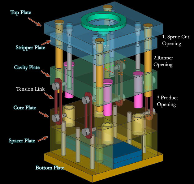
A molding according to the function of each of its parts can be divided into four sections
1. Introductory part of the plastic nozzle into the cavity cavity
2. penunjuang system (support system)
3. demolding system
4. heat transfer system
In the manufacture of injection mold, mold base is an integral part, mold maker can make your own mold base or buy a standard mold base, the system of the mold base can be adjusted with the construction standards required, both for the two plate and three plate, stripper plate ejectors, hot runner and mold base for a screw, when the entire standard mold base is not there to meet the new final step is to make a special mold base.
classification or types of mold injection very depend on what we need to make the plastic parts, because every parts have specific and unique design. when design molds we must see what the influencing factor like geometry, number of cavities, ejection principle, plastic material and shape of part.
This section is the most important part of the overall mold cylcle time, because in one cycle time, the process of heat exchange to spend about 70-80% of the total cycle time, thus setting the optimal heat transfer system will greatly affect the quality and cycle time of a product.
cavity and core, and its derivatives when there are undercut on product, design and construction of a good core cavity and in accordance with the requirement could increase the life of tooling itself, reduce material consumption, reduce dependence on maintenance inserts, and can reduce the cost of making the mold so the mold cost per products also declined.
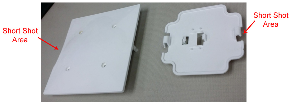
this type of defect is caused by A molded product that is incomplete because the mold cavity was not filled completely. If a part short shots, the plastic does not fill the cavity. The flow freezes off before the flow paths have completely filled.
commonly the main caused could device in two main problem One of these occurs because, in the middle of the flow of the molten plastic, the front end of the flow gets cooled and solidifies. The second is caused, in the flow process of the molten plastic, because air traps are generated in the flow depending on the conditions of the flow.
sample short shot
Molding equipment
Increase the amount of material feed. If material feed is still insufficient at maximum material feed capacity, change to a larger capacity machine. Install a screw with a back-flow check valve. Increase injection pressure Raise the cylinder temperature setting. Raise the nozzle temperature, too. Make sure there are no severed lines to the heater. Make sure the nozzle is not clogged. If the nozzle clogs frequently, raise the mold temperature or shorten the cycle time. Increase injection speed
Mold
Raise the mold temperature. Increase the mold gas release. Increase gate cross section surface area. Increase the molded product thickness. Add ribs to the molded product design to improve flowability. Choose a low-viscosity high flow material type. Apply surface lubricant. (Add 0.05-0.1% by weight.)
Various way available to calculate cooling time in injection mould, the easiest way of course using numerical method, software package like mold flow, C - mold or your own compile numerical method language also available in the market, for detail and specific calculation, i suggest to write your own equation base on the problem, after that write in the programming language and understanding the result for the next optimization.
Why Cooling?
Plastic industry is one of the world’s fastest growing industries, ranked as one of the few billion-dollar industries. Almost every product that is used in daily life involves the usage of plastic and most of these products can be produced by plastic injection molding method. Injection molding represents the most important process for manufacturing plastic parts. It is suitable for mass-producing products, since raw material can be converted into a molding by single procedure The plastic injection molding process is a cyclic process.[1]
The cooling phase of the injection moulding process accounts for up to 75% of the overall cycle time. It therefore follows that a reduction in cooling time will in turn reduce the overall cycle time and hence, increase the throughput rate
Experimentally, cooling times are defined as the time taken for the pressure at the primary sensor to return to atmospheric, after the injection of a consecutive shot. The molten polymer cools and solidifies in the mould [2]
The cooling system design was primarily based on the experience of the designer but the development of new rapid prototyping process makes possible to manufacture very complex channel shapes what makes this empirical former method inadequate. So the design of the cooling system must be formulated as an optimization problem
The heat-transfer processes which occur in the plastic part and in the mould during the injection moulding of thermoplastics are rather complex. The situation is one of three-dimensional unsteady-state heat-transfer with a phase change.
Determining Cooling Time Formula
Ballman and Shusman method,
they proposed this formula to calculate cooling time for injection mould process
where t is the cooling time in seconds: S is the maximum cavity thickness, mm; alfa is the diffusivity, 0i is the melt temperature at injection, °C; 0w is the mould temperature, °C; and 0e is the ejection temperature, °C, the latter being taken to be the heat deflect temperature (HDT) of the thermoplastic. However, it is recognized that the HDT is not a material constant but is dependent strongly on the processing pressure and sample thickness as well as on the type of material.[3]
Busch, Field and Rosato Method,
they proposed a combination of theoretical and statistical methods to derive the following equation for estimating the cooling time
Wp is part weight and Ncav is the number of cavities of the mould.
Kirch and Menges Method
commonly use in semi crystalline material [5]
J.Z. Liang and J.N. Ness Method
they use new formula base on analytical method,by judicious selection of the representative ejection temperature, the following equation for determining the cooling time of a polymer part in injection moulding can be derived
another formula also variable in many article and journal of material processing, because limited literature that i have, some month a go i also read calculation cooling time method from Professor in Japan and Korea, but, i forget to save those journal.
Which one the best?
i think to find with one the best, we must compare various formula with same temperature of ejection and other parameter we set same, than we compare the result with recommended or actual setting in injection process, of course with same material type.
Reference
[1]. S.H. Tang, Y.M. Kong, S.M. Sapuan, R. Samin, S. Sulaiman, Design and thermal analysis of plastic injection mold, J. Mater. Process. Technol. 171 (2006) 259–267
[2] A.G. Smith et al, A computational model for the cooling phase of injection moulding.
[3] C.J. Yu, J.E. Sunderland, Polym. Engng Sci., 32 (1992) 191.
[4] J. Busch, F. Field, Ill, and D. Rosato, Proc. SPE RETEC, Boston, Vol. 1, 1988
[5] G. Wubken and 1. Catic, Kunst~'-Berater
Jetting occurs when polymer melt is pushed at a high velocity through restrictive areas, such as the nozzle, runner, or gate, into open, thicker areas, without forming contact with the mold wall. The buckled, snake-like jetting stream causes contact points to form between the folds of melt in the jet, creating small-scale "welds".
Jetting leads to part weakness, surface blemishes, and a multiplicity of internal defects. [1]
Mainly Caused by
Excessive ram speed,
Poor gate position
,Lack of melt contact with the mold allows jetting to occur,
Inadequate hot runner system design
Excessive Injection Speed
Explanation: Excessive injection speed (fill rate) will cause the molten plastic to form jet streams as it is pushed through the gates instead of the more desirable wide "tongue'' of material. These snake-like streams cool independently from the surrounding material and are visible on the molded part surface.
Solution: Reducing the injection speed will allow the plastic flow front to stay together and not form the individual streams that cause the jetting patterns on the part surface.
Barrel Temperature Too High or Too Low
Explanation: When barrel temperatures are too low, the material will not be heated to the proper temperature for adequate flow. The material will push slowly into the mold and the flow front will break up into individual streams as resistance builds up. This will cause jetting patterns. On the other hand, if the barrel temperature is too high, the material is pushed into the mold too quickly. This causes the flow front to split apart as it enters the cavity and the jetting patterns will develop.
Solution: Decrease or increase the barrel temperature accordingly. The material supplier can recommend the best starting point for barrel temperature and it can be adjusted from that point. Make changes in 10 degree F increments and keep the profile so it is heating progressively from back to front.
Small Nozzle Opening
Explanation: If the nozzle opening (or sprue bushing opening) is too small for the material being molded, the restriction may cause the material to flow too slowly and solidify early. The flow front may break apart as it travels through the gate (due to sidewall friction) and jetting patterns may develop.
Solution: Increase the nozzle opening. As a general rule, the nozzle opening should never be less than 7/32'' in diameter. The stiffer the material flow, the larger that opening should be. Make sure that the sprue bushing opening diameter matches or is 1/32'' larger than the nozzle opening.
Low Nozzle Temperature
Explanation: As material is transported through the heating barrel, it is gradually brought up to the ideal processing temperature by absorbing heat from the heating bands and frictional heat, which is created by the shearing action of the rotating screw within the barrel. In the last heating zone, the material is exposed to is the nozzle. By the time the material gets to the nozzle, it should already be at ideal molding temperature and only a small amount of heat needs to be applied at this point to keep the resin flowing. If the nozzle is not hot enough, however, the material will begin to cool off too quickly as it leaves the barrel and the flow front will not flow properly, breaking into many streams and causing jetting.
Solution: Increase the nozzle temperature. As a rule-of-thumb the nozzle temperature should be set at 10 degrees F higher than the setting for the front zone of the barrel. This helps compensate for heat loss due to metal-to-metal contact between the nozzle and the sprue bushing and keeps the material hot enough to flow properly, eliminating jetting.
MOLD
Low Mold Temperature
Explanation: Generally, a hot mold will allow a material to stay molten longer than a cold mold and cause the molecules to pack together properly before they solidify. This results in a dense part with no separation of layers. If the mold is too cold, the molecules solidify before they are packed together and may break up into separate units. As they travel through the gate these units split up and form jetting patterns on the part surface.
Solution: Increase the mold temperature to the point at which the material has the proper flow and packs out the mold without jetting. Start with the material suppliers recommendations and adjust accordingly. Allow 10 cycles for every 10-degree change for the process to re-stabilize.
Small Gates and/or Runners
Explanation: Gates and/or runners that are too small will cause excessive restriction to the flow of the molten plastic. Many plastics will then begin to solidify before they fill the cavity. The result is an unpacked condition and the flow front may break into separate streams, causing jetting patterns to develop.
Solution: Examine the gates and runners to determine if any burrs or other obstructions exist. If possible, perform a computer analysis to determine the proper sizing and location of gates and runners. Ask the material supplier for data concerning gate and runner dimensioning for a specific material and flow rate.
Improper Gate Location
Explanation: If certain materials are injected directly across a flat cavity surface they tend to slow down quickly as a result of frictional drag and cool off before the cavity is properly filled. As the material tries to flow through the gate, it is pulled apart into several streams and this forms a jetting pattern on the part.
Solution: Relocate, or redesign, the gate so that the molten plastic is directed against an obstruction such as a core pin. This will cause the material to disperse and continue to flow instead of slowing down.
Excessive Gate Land Length
Explanation: The area that surrounds the gate itself is called its land. It determines the distance a material must travel in a restricted state immediately before it enters the cavity. The length of this travel (land) should be no more than 1/8''. The land acts like a tunnel when the mold is closed and if the tunnel is too ling the material begins to cool off before it can get to the cavity. This causes the material to split into streams that create the familiar jetting pattern on the part.
Solution: Decrease the gate land length. It is best to construct the mold so that the gates are located in replaceable inserts. That way they can be replaced easily at times when adjustments are needed. The insert should include the land area. This land length should be no less than 0.030'' and no greater than 0.125''.
MATERIAL
Improper Flow Rate
Explanation: Resin manufacturers supply specific formulations in a range of standard flow rates. Thin-walled products may require an easy flow material while thick-walled products can use a material that is stiffer. It is better to use as stiff a flow as possible because that improves physical properties of the molded part. But, the stiff material will be more difficult to push and this may result in a breakup of the flow front as the material enters the gate. The breakup appears as a jetting pattern.
Solution: Utilize a material that has the stiffest flow possible without causing jetting. Contact the material supplier for help in deciding which flow rate should be used for a specific application.
OPERATOR
Inconsistent Process Cycle
Explanation: It is possible that the machine operator is the cause of delayed or inconsistent cycles. This will result in erratic heating of the material in the injection barrel. If such a condition exists, the colder particles may not fill the mold before they fully solidify. Jetting may be caused as these colder areas attempt to push through the gate and are torn apart due to sidewall friction.
Solution: If possible, run the machine on the automatic cycle, using the operator only to interrupt the cycle if an emergency occurs. Use a robot if an ``operator'' is necessary. In addition, instruct all employees on the importance of maintaining
Reference
1. BASF, Injection Moudling Process Solution, Mold Problem Catalog
2. Robert A.M Plastic Part Design for Injection Mould, an Introduction, Hanser
3. Misumi Tech Central : http://www.misumi-techcentral.com/tt/en/mold/2010/02/031-jetting.html
4. Injection Molding Guide : http://www.kenplas.com/service/imtroubleshooting.aspx
5. Sabiq Innovative Plastic
6. Various journal from Elsevier
this post shows the flashing process occurs in the injection mold, in fact many things that influence the occurrence of the flash, but can be broadly divided into 3
1. material effect
2. Influence of the injection mold
3. Effect of mold conditions
for example, due to the influence of material, rubber and PP is certainly more difficult to control defects in flash because it has a low viscosity compared to PBT, or Xyron.
because of mold flash, can be caused by several things, among others
1. mold core thickness is insufficient, causing deflection while receiving the injection from the nozzle. this can be avoided by calculating the estimated deflection and also adds support pillar between the bottom plate with the core plate.
2. machining is not good, if this happens core or cavity must be measured first, then rewelding and re-machining.
3. if for the wrong polishing process, so that the bumpy surface (waves), surface machining has to be repeated, is made insert core, can also rewelding.
of course, before doing the repair process because of flash, we must first check the cause, either in the injection process, and the molding itself.
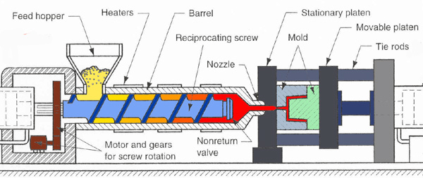
I found a great video from youtube, although it was on youtube a while, but this video deserves to be given the thumbs.
in this video can be seen clearly how the process of formation at the injection mold part to work, well we'll find out in detail the process of melting and movement of the screw on the injection machine
rapid heat temperature, is actually an old method that is often used to eliminate the weld line, the front cover products such as TV, is an example of the most frequently used method, but its use is now developed further, as demand for products with low cycle time and quality of surface nice sharp increase lately, covering progress being made is that the control system is used, so the heat on the heating rod is held constant, the only heating occurs during the process of filling, so filling process stops, and the cooling process is done, no heating rod heating process.
Advantage
Trim cycle times up to 20 %
A new unit combines rapid heating and cooling and mold-temperature control in one unit as a means to trim cycle times by up to 20% and reduce energy cost. It is the result of a collaboration between Wieder GmbH International of Germany, a supplier of pulsed mold heating/cooling systems, and Regloplas of Switzerland, a maker of fluid temperature-control units
Reduce Weld line
because during the process of filling, the mold is heated, especially at the regional meeting of the plastic, this led to the solidification of the material evenly, so that the weld line can be minimized.
injection mold is rapidly heated to a high temperature, usually higher than the glass transition temperature of the polymer material, before melt-injection and rapidly cooled down to solidify the shaped polymer melt in mold cavity for ejection. Since the elevated mold temperature can eliminate the unwanted premature melt freezing during filling stage, the melt flow resistance is greatly reduced and the filling ability of the polymer melt is also significantly improved. As a result, plastic parts with excellent surface appearance can be obtained.
Improve Appearance
rapid heat cycle method is also shown to improve the quality of the surface, this is because the process of filling with stable temperatures ranging from the gate to the end product, or it could be said to be due to differences in temperature in the cavity is not much different.
Reduce Cost
I was not sure whether this method can reduce the cost of production, when production is carried out is to a large scale, of course, 10-20% reduction in cycle time will bring a lot of meaning to the cost of production, but when the scale of SMEs, given the initial price for the application of this method expensive, I think this method will not reduce production costs.
Heating Method
various types of heating methods research has been carried out
1. use of the insulation layer, An insulation layer is coated onto the mold base then a heating layer is applied to the insulation layer as the cavity surface, for Increasing the mold surface temperature in the filling process, a coating on the cavity surfacewith TiN and Teflon has reduced the heat transfer from the melt to the mold material, the which Increased the temperature on the cavity surface.
2. the use of steam. difficulty of this method is the first installation costs are expensive, and slow increase in temperature,
3. Infrared radiation on the surface, this method has also been investigated, and are able to reduce cycle time by 20%
4. electric heating rod, this method is the method most commonly used in industry because of the installation, maintenance, repairs are relatively easy. but the price per Kw electricity is relatively expensive, because it takes a minimum of 300 watts for a heating rod.
Reference
1. S.C. Chen, H.S. Peng, J.A. Chang, W.R. Jong, Simulation and verification of induction
heating on a mold plate, International Communications in Heat and Mass Transfer
31 (7) (2004) 971–980.
2. P.C. Chang, S.J. Hwang, Simulation of infrared rapid surface heating for injection
molding, International Journal of Heat and Mass Transfer 49 (21–22) (2006)
3846–3854.
3. G.L. Wang, G.Q. Zhao, H.P. Li, Y.J. Guan, Research of thermal response simulation
and mold structure optimization for rapid heat cycle molding process,
respectively, with steam heating and electric heating, Materials and Design 31
(1) (2010) 382–395.
4. X.P. Li, G.Q. Zhao, Y.J. Guan, M.X. Ma, Optimal design of heating channels for rapid
heating cycles injection mold based on response surface and genetic algorithm,