Injection Mould Construction

A molding according to the function of each of its parts can be divided into four sections 1. Introductory part of the plastic nozzle into the cavity cavity 2. penunjuang system (support system) 3. demolding system 4. heat transfer system

Mold Base Standard Part

In the manufacture of injection mold, mold base is an integral part, mold maker can make your own mold base or buy a standard mold base, the system of the mold base can be adjusted with the construction standards required, both for the two plate and three plate, stripper plate ejectors, hot runner and mold base for a screw, when the entire standard mold base is not there to meet the new final step is to make a special mold base.

Injection Mould Classification

classification or types of mold injection very depend on what we need to make the plastic parts, because every parts have specific and unique design. when design molds we must see what the influencing factor like geometry, number of cavities, ejection principle, plastic material and shape of part.

Injection Mold Cooling

This section is the most important part of the overall mold cylcle time, because in one cycle time, the process of heat exchange to spend about 70-80% of the total cycle time, thus setting the optimal heat transfer system will greatly affect the quality and cycle time of a product.

Undercut System : Cam, Angular, Lift Cavity, Loose core

cavity and core, and its derivatives when there are undercut on product, design and construction of a good core cavity and in accordance with the requirement could increase the life of tooling itself, reduce material consumption, reduce dependence on maintenance inserts, and can reduce the cost of making the mold so the mold cost per products also declined.

Sunday, September 17, 2017

Short shot or short molded Defect Product

this type of defect is caused by A molded product that is incomplete because the mold cavity was not filled completely. If a part short shots, the plastic does not fill the cavity. The flow freezes off before the flow paths have completely filled.


commonly the main caused could device in two main problem One of these occurs because, in the middle of the flow of the molten plastic, the front end of the flow gets cooled and solidifies. The second is caused, in the flow process of the molten plastic, because air traps are generated in the flow depending on the conditions of the flow.


sample short shot


Molding equipment

Increase the amount of material feed. If material feed is still insufficient at maximum material feed capacity, change to a larger capacity machine.
Install a screw with a back-flow check valve.
Increase injection pressure
Raise the cylinder temperature setting. Raise the nozzle temperature, too.
Make sure there are no severed lines to the heater.
Make sure the nozzle is not clogged. If the nozzle clogs frequently, raise the mold temperature or shorten the cycle time.
Increase injection speed

Mold

Raise the mold temperature.
Increase the mold gas release.
Increase gate cross section surface area.
Increase the molded product thickness.
Add ribs to the molded product design to improve flowability.
Choose a low-viscosity high flow material type.
Apply surface lubricant. (Add 0.05-0.1% by weight.)

Saturday, July 21, 2012

The calculation of cooling time in injection moulding

Various way available to calculate cooling time in injection mould, the easiest way of course using numerical method, software package like mold flow, C - mold or your own compile numerical method language also available in the market, for detail and specific calculation, i suggest to write your own equation base on the problem, after that write in the programming language and understanding the result for the next optimization.

Why Cooling?

 Plastic industry is one of the world’s fastest growing industries, ranked as one of the few billion-dollar industries. Almost every product that is used in daily life involves the usage of plastic and most of these products can be produced by plastic injection molding method. Injection molding represents the most important process for manufacturing plastic parts. It is suitable for mass-producing products, since raw material can be converted into  a molding by single procedure The plastic injection molding process is a cyclic process.[1]
The cooling phase of the injection moulding process accounts for up to 75% of the overall cycle time. It therefore follows that a reduction in cooling time will in turn reduce the overall cycle time and hence, increase the throughput rate
Experimentally, cooling times are defined as the time taken for the pressure at the primary sensor to return to atmospheric, after the injection of a consecutive shot. The molten polymer cools and solidifies in the mould [2]
The cooling system design was primarily based on the experience of the designer but the development of new
rapid prototyping process makes possible to manufacture very complex channel shapes what makes this empirical
former method inadequate. So the design of the cooling system must be formulated as an optimization problem
The heat-transfer processes which occur in the plastic part and in the mould during the injection moulding of
thermoplastics are rather complex. The situation is one of three-dimensional unsteady-state heat-transfer with a
phase change.

Determining Cooling Time Formula

Ballman and Shusman method, 

they proposed this formula to calculate cooling time for injection mould process
where t is the cooling time in seconds: S is the maximum cavity thickness, mm; alfa is the diffusivity, 0i is the melt temperature at injection, °C; 0w is the mould temperature, °C; and 0e is the ejection temperature, °C, the latter being taken to be the heat deflect temperature (HDT) of the thermoplastic. However, it is recognized that the HDT is not a material constant but is dependent strongly on the processing pressure and sample thickness as well as on the type of material.[3]

Busch, Field and Rosato Method,

they proposed a combination of theoretical and statistical methods to derive the following equation for estimating the cooling time
Wp is part weight and Ncav is the number of cavities of the mould.

Kirch and Menges Method

commonly use in semi crystalline material [5]

J.Z. Liang and J.N. Ness Method

they use new formula base on analytical method,by judicious selection of the representative ejection temperature, the following equation for determining the cooling time of a polymer part in injection moulding can be derived
another formula also variable in many article and journal of material processing, because limited literature that i have, some month a go i also read calculation cooling time method from Professor in Japan and Korea, but, i forget to save those journal.

Which one the best?

i think to find with one the best, we must compare various formula with same temperature of ejection and other parameter we set same, than we compare the result with recommended or actual setting in injection process, of course with same material type.

Reference

[1]. S.H. Tang, Y.M. Kong, S.M. Sapuan, R. Samin, S. Sulaiman, Design and thermal analysis of plastic injection mold, J. Mater. Process. Technol. 171 (2006) 259–267
[2]  A.G. Smith et al,  A computational model for the cooling phase of injection moulding.
[3] C.J. Yu, J.E. Sunderland, Polym. Engng Sci., 32 (1992) 191.
[4] J. Busch, F. Field, Ill, and D. Rosato, Proc. SPE RETEC, Boston, Vol. 1, 1988
[5] G. Wubken and 1. Catic, Kunst~'-Berater


how jetting occur on molding process


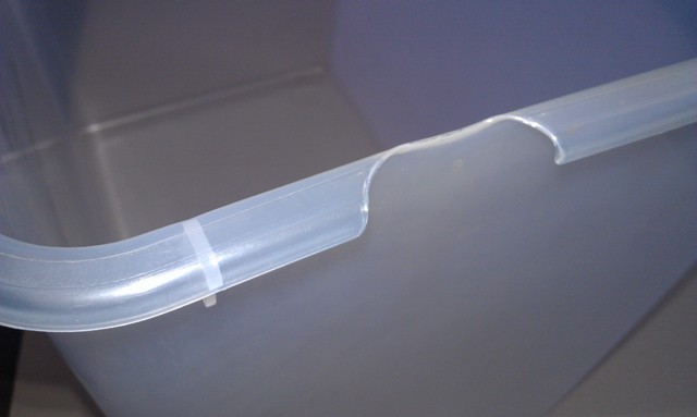
Jetting occurs when polymer melt is pushed at a high velocity through restrictive areas, such as the nozzle, runner, or gate, into open, thicker areas, without forming contact with the mold wall. The buckled, snake-like jetting stream causes contact points to form between the folds of melt in the jet, creating small-scale "welds". Jetting leads to part weakness, surface blemishes, and a multiplicity of internal defects. [1]
Mainly Caused by Excessive ram speed, Poor gate position ,Lack of melt contact with the mold allows jetting to occur, Inadequate hot runner system design

 Excessive Injection Speed


Explanation: Excessive injection speed (fill rate) will cause the molten plastic to form jet streams as it is pushed through the gates instead of the more desirable wide "tongue'' of material. These snake-like streams cool independently from the surrounding material and are visible on the molded part surface.

Solution: Reducing the injection speed will allow the plastic flow front to stay together and not form the individual streams that cause the jetting patterns on the part surface.

Barrel Temperature Too High or Too Low


Explanation: When barrel temperatures are too low, the material will not be heated to the proper temperature for adequate flow. The material will push slowly into the mold and the flow front will break up into individual streams as resistance builds up. This will cause jetting patterns. On the other hand, if the barrel temperature is too high, the material is pushed into the mold too quickly. This causes the flow front to split apart as it enters the cavity and the jetting patterns will develop.

Solution: Decrease or increase the barrel temperature accordingly. The material supplier can recommend the best starting point for barrel temperature and it can be adjusted from that point. Make changes in 10 degree F increments and keep the profile so it is heating progressively from back to front.

Small Nozzle Opening


Explanation: If the nozzle opening (or sprue bushing opening) is too small for the material being molded, the restriction may cause the material to flow too slowly and solidify early. The flow front may break apart as it travels through the gate (due to sidewall friction) and jetting patterns may develop.

Solution: Increase the nozzle opening. As a general rule, the nozzle opening should never be less than 7/32'' in diameter. The stiffer the material flow, the larger that opening should be. Make sure that the sprue bushing opening diameter matches or is 1/32'' larger than the nozzle opening.

Low Nozzle Temperature


Explanation: As material is transported through the heating barrel, it is gradually brought up to the ideal processing temperature by absorbing heat from the heating bands and frictional heat, which is created by the shearing action of the rotating screw within the barrel. In the last heating zone, the material is exposed to is the nozzle. By the time the material gets to the nozzle, it should already be at ideal molding temperature and only a small amount of heat needs to be applied at this point to keep the resin flowing. If the nozzle is not hot enough, however, the material will begin to cool off too quickly as it leaves the barrel and the flow front will not flow properly, breaking into many streams and causing jetting.

Solution: Increase the nozzle temperature. As a rule-of-thumb the nozzle temperature should be set at 10 degrees F higher than the setting for the front zone of the barrel. This helps compensate for heat loss due to metal-to-metal contact between the nozzle and the sprue bushing and keeps the material hot enough to flow properly, eliminating jetting.


MOLD


Low Mold Temperature


Explanation: Generally, a hot mold will allow a material to stay molten longer than a cold mold and cause the molecules to pack together properly before they solidify. This results in a dense part with no separation of layers. If the mold is too cold, the molecules solidify before they are packed together and may break up into separate units. As they travel through the gate these units split up and form jetting patterns on the part surface.

Solution: Increase the mold temperature to the point at which the material has the proper flow and packs out the mold without jetting. Start with the material suppliers recommendations and adjust accordingly. Allow 10 cycles for every 10-degree change for the process to re-stabilize.

Small Gates and/or Runners


Explanation: Gates and/or runners that are too small will cause excessive restriction to the flow of the molten plastic. Many plastics will then begin to solidify before they fill the cavity. The result is an unpacked condition and the flow front may break into separate streams, causing jetting patterns to develop.

Solution: Examine the gates and runners to determine if any burrs or other obstructions exist. If possible, perform a computer analysis to determine the proper sizing and location of gates and runners. Ask the material supplier for data concerning gate and runner dimensioning for a specific material and flow rate.

Improper Gate Location


Explanation: If certain materials are injected directly across a flat cavity surface they tend to slow down quickly as a result of frictional drag and cool off before the cavity is properly filled. As the material tries to flow through the gate, it is pulled apart into several streams and this forms a jetting pattern on the part.

Solution: Relocate, or redesign, the gate so that the molten plastic is directed against an obstruction such as a core pin. This will cause the material to disperse and continue to flow instead of slowing down.

Excessive Gate Land Length


Explanation: The area that surrounds the gate itself is called its land. It determines the distance a material must travel in a restricted state immediately before it enters the cavity. The length of this travel (land) should be no more than 1/8''. The land acts like a tunnel when the mold is closed and if the tunnel is too ling the material begins to cool off before it can get to the cavity. This causes the material to split into streams that create the familiar jetting pattern on the part.

Solution: Decrease the gate land length. It is best to construct the mold so that the gates are located in replaceable inserts. That way they can be replaced easily at times when adjustments are needed. The insert should include the land area. This land length should be no less than 0.030'' and no greater than 0.125''.

MATERIAL


Improper Flow Rate


Explanation: Resin manufacturers supply specific formulations in a range of standard flow rates. Thin-walled products may require an easy flow material while thick-walled products can use a material that is stiffer. It is better to use as stiff a flow as possible because that improves physical properties of the molded part. But, the stiff material will be more difficult to push and this may result in a breakup of the flow front as the material enters the gate. The breakup appears as a jetting pattern.

Solution: Utilize a material that has the stiffest flow possible without causing jetting. Contact the material supplier for help in deciding which flow rate should be used for a specific application.

OPERATOR


Inconsistent Process Cycle

Explanation: It is possible that the machine operator is the cause of delayed or inconsistent cycles. This will result in erratic heating of the material in the injection barrel. If such a condition exists, the colder particles may not fill the mold before they fully solidify. Jetting may be caused as these colder areas attempt to push through the gate and are torn apart due to sidewall friction.

Solution: If possible, run the machine on the automatic cycle, using the operator only to interrupt the cycle if an emergency occurs. Use a robot if an ``operator'' is necessary. In addition, instruct all employees on the importance of maintaining

Reference
1. BASF, Injection Moudling Process Solution, Mold Problem Catalog
2. Robert A.M Plastic Part Design for Injection Mould, an Introduction, Hanser
3. Misumi Tech Central : http://www.misumi-techcentral.com/tt/en/mold/2010/02/031-jetting.html
4. Injection Molding Guide : http://www.kenplas.com/service/imtroubleshooting.aspx
5. Sabiq Innovative Plastic
6. Various journal from Elsevier

Sunday, June 3, 2012

how flash occurs on mould?

this post shows the flashing process occurs in the injection mold, in fact many things that influence the occurrence of the flash, but can be broadly divided into 3
1. material effect
2. Influence of the injection mold
3. Effect of mold conditions
for example, due to the influence of material, rubber and PP is certainly more difficult to control defects in flash because it has a low viscosity compared to PBT, or Xyron. because of mold flash, can be caused by several things, among others
1. mold core thickness is insufficient, causing deflection while receiving the injection from the nozzle. this can be avoided by calculating the estimated deflection and also adds support pillar between the bottom plate with the core plate.
2. machining is not good, if this happens core or cavity must be measured first, then rewelding and re-machining.
3. if for the wrong polishing process, so that the bumpy surface (waves), surface machining has to be repeated, is made insert core, can also rewelding.
of course, before doing the repair process because of flash, we must first check the cause, either in the injection process, and the molding itself.

Wednesday, May 2, 2012

Video basic understanding of injection mould

I found a great video from youtube, although it was on youtube a while, but this video deserves to be given the thumbs.
in this video can be seen clearly how the process of formation at the injection mold part to work, well we'll find out in detail the process of melting and movement of the screw on the injection machine

Saturday, April 7, 2012

rapid heat cooling system on injection mold

rapid heat temperature, is actually an old method that is often used to eliminate the weld line, the front cover products such as TV, is an example of the most frequently used method, but its use is now developed further, as demand for products with low cycle time and quality of surface nice sharp increase lately, covering progress being made is that the control system is used, so the heat on the heating rod is held constant, the only heating occurs during the process of filling, so filling process stops, and the cooling process is done, no heating rod heating process.

Advantage

Trim cycle times up to 20 %
A new unit combines rapid heating and cooling and mold-temperature control in one unit as a means to trim cycle times by up to 20% and reduce energy cost. It is the result of a collaboration between Wieder GmbH International of Germany, a supplier of pulsed mold heating/cooling systems, and Regloplas of Switzerland, a maker of fluid temperature-control units
Reduce Weld line
because during the process of filling, the mold is heated, especially at the regional meeting of the plastic, this led to the solidification of the material evenly, so that the weld line can be minimized.
injection mold is rapidly heated to a high temperature, usually higher than the glass transition temperature of the polymer material, before melt-injection and rapidly cooled down to solidify the shaped polymer melt in mold cavity for ejection. Since the elevated mold temperature can eliminate the unwanted premature melt freezing during filling stage, the melt flow resistance is greatly reduced and the filling ability of the polymer melt is also significantly improved. As a result, plastic parts with excellent surface appearance can be obtained.
Improve Appearance
rapid heat cycle method is also shown to improve the quality of the surface, this is because the process of filling with stable temperatures ranging from the gate to the end product, or it could be said to be due to differences in temperature in the cavity is not much different.
Reduce Cost
I was not sure whether this method can reduce the cost of production, when production is carried out is to a large scale, of course, 10-20% reduction in cycle time will bring a lot of meaning to the cost of production, but when the scale of SMEs, given the initial price for the application of this method expensive, I think this method will not reduce production costs.

Heating Method

various types of heating methods research has been carried out
1. use of the insulation layer, An insulation layer is coated onto the mold base then a heating layer is applied to the insulation layer as the cavity surface, for Increasing the mold surface temperature in the filling process, a coating on the cavity surfacewith TiN and Teflon has reduced the heat transfer from the melt to the mold material, the which Increased the temperature on the cavity surface.
2. the use of steam. difficulty of this method is the first installation costs are expensive, and slow increase in temperature,
3. Infrared radiation on the surface, this method has also been investigated, and are able to reduce cycle time by 20%
4. electric heating rod, this method is the method most commonly used in industry because of the installation, maintenance, repairs are relatively easy. but the price per Kw electricity is relatively expensive, because it takes a minimum of 300 watts for a heating rod.

Reference
1. S.C. Chen, H.S. Peng, J.A. Chang, W.R. Jong, Simulation and verification of induction
heating on a mold plate, International Communications in Heat and Mass Transfer
31 (7) (2004) 971–980.
2. P.C. Chang, S.J. Hwang, Simulation of infrared rapid surface heating for injection
molding, International Journal of Heat and Mass Transfer 49 (21–22) (2006)
3846–3854.
3. G.L. Wang, G.Q. Zhao, H.P. Li, Y.J. Guan, Research of thermal response simulation
and mold structure optimization for rapid heat cycle molding process,
respectively, with steam heating and electric heating, Materials and Design 31
(1) (2010) 382–395.
4. X.P. Li, G.Q. Zhao, Y.J. Guan, M.X. Ma, Optimal design of heating channels for rapid
heating cycles injection mold based on response surface and genetic algorithm,
Materials and Design 30 (10) (2009) 4317–4323.

Friday, March 23, 2012

Cooling Layout and Cooling method between core/cavity and mold base

Cooling is most important parameter when talking about cycle time reduce, some of my friend who very interest in injection mould still confuse how to design cooling system in injection mould, before talking about optimal design, first we must be familiar with the term and design standard that will be used.
Basic Cooling Layout

in principle, the more uniform temperature in the cavity, the better the resulting product, the more uniform and rapid heat transfer processes during the process of solidification occurs, the faster the cooling process, and of course the faster the cycle time that happened.when designing, to keep the cooling process is rapid and uniform cooling channels should be sought closer to the wall of the product, especially for regions of high and thick walls. therefore the cavity cooling channels is essential.

in the image above, is an example of basic connections cooling layout, its parts are
A. cavity colored with blue
2. green is mold base
3. yellow is cooling joint plug
4. white is hose connection to connecting cooling joint plug

on the left side of mold in above picture, we see that two pcs of cooling joint plug (yellow color) in that side, is for input and output of cooling mold base and cooling channel from the machine.

Rectangle Like Layout
depend one cooling layout is a favorite around the product, because the drilling process should be straight, then the shape is rectangle, except in the form of circular gear will be retained.

Friday, February 10, 2012

Injection Mould Venting System, a little part of design that have big effect on part quality

venting is a small part of the mold design, on the design process also requires a very short time, perhaps only 10% or less of the total time required in designing.sometimes is frequently neglected until molding trials indicate mold inadequacies related to venting. if we understand the purpose and function of vents, it's can assists mold designer to design where clearly additional vents required.

when the cavity space injected by plastic material, automatically empty space on the cavity will be filled with plastic material, the air in the cavity will be shifted to another place, what would happen if the air can not move, the air will experience a high pressure , so the temperature rises even higher, resulting in plastic that fills the cavity will be burning, the defect is called a burn, because of the importance of venting a lot of products that fail due to not properly inject the gas vent, especially for products that have a rib that thin and tall, as compared to thick products.


source : Plastic Today


The main function of the venting is
A. compressed air release
when compressed air is not expelled from the cavity, the plastic flow is inhibited, the result will be formed on a short shot of the product
2. compressed air will produce a gas with high temperature and burn the plastic around it, resulting in a defect burn marks, the product looks like a burn, this will greatly affect the look of the product.
3. when the gas mixed with plastic, the plastic will generate an uneven structure, which will reduce the strength of the product / mold parts produced, stress concentration also common in this region, which occurs due to the plastic notch.


for more detail about effect of adequate of venting on injection mold, please see on picture below


part of venting, can divide on 2 section, land and groove, land is always contact with plastic melt, it's deep about 0.01 mm until 0.02 mm, depend on viscosity of material, relief of vent or gas land is about 1 mm until 2mm, but you must remember for rubber all the number above can't applied, gas vent on rubber material is very special, because rubber has low viscosity.
when designing the gas vent / venting on injection mould, make sure that all of the groove must have exhaust groove that connect to atsmosfer.

Monday, November 21, 2011

collapsible core for demolding/ejection system of internal screw undercut

one common way used in the ejection system for an internal screw is used collabsible undercut core, which requires collabsible core product generally has the undercut on the inside, for example an internal screw, pipe fittings, elbow pipe, use collabsibe core is not only on the core course , undercut the slider is also often used collabsible cores.
video below gives a simple explanation of how Collapsible cores working

http://www.die-moldtool.com/

Main Component
The three units are a Collapsible Core, center pin, and a positive collapse sleeve.

cenTer pin
The Center Pin serves to expand the segments of the Collapsible Core to their molding position and holds them at this diameter. A hole is provided inside the pin for cooling. The center pin is manufactured of a high alloy Type D-6 steel hardened to 60 to 65 Rockwell C or use SKH 51, SKD 11. Refer to the pin grinding instructions for machining directions. In use the pin must incorporate two design features. The pin must protrude beyond the face of the collapsing core segments by certain amounts. This protrusion keeps material from flowing under the face of the collapsing segments to ensure they properly collapse. A radius must be applied to the outside corner at the front of the center pin. The sharp edge resulting from cutting the pin to length will gall and subsequently destroy the inside surfaces of the collapsing core segments
collapsible core
The Collapsible Core is manufactured from A.I.S.I. Type A-2 steel hardened to 51 to 57 Rockwell C. It is designed to collapse independently when the center pin is withdrawn. The fit between segments is controlled to permit flash free molding. The location of the core on its pin is critical. The distance between the back of the core flange and the front of the center pin flange (Head Space) is critical and must be maintained.
If the Head Space (1.938 ±.005 on a CC 202 PC) is not maintained, unsatisfactory operation will result, or the core may be permanently damaged.
posiTive collapse sleeve
The Positive Collapse Sleeve (PC sleeve) is designed to function when the Collapsible Core fails to collapse independently upon withdrawal of the center pin. In normal operation, the PC sleeve is not functioning. It is essential to have such a unit for maximum safety and reliability in automatic and semi-automatic operation. Under no circumstances should a mold be placed into automatic operation without the use of the PC sleeve.


picture above shown collapsible core and the component, detail explanation about CC we can find it in DME standard part http://www.dme.net/dme/resources/FAQs/collapse_cores.html

Wednesday, June 29, 2011

Runner Design in Injection Mold,


in designing the runner, first-time we must consider items that affecting  runnersize, some of which
- Volume of part, the greater the volume takes a larger diameter runners anyway.
- Weight of part, the heavier parts, it takes a larger diameter runners.
- Plastic materials, plastic materials with low viscosity, aqueous requires a smallerdiameter runner.
- Wall thickness, the thicker the greater the diameter of the runner is needed.
- Length of flow path, the longer it takes the flow of large diameter runner.


picture above shown some factor that we must consider before choosing right diameter of runner, 

Cross Section Area
various cross section area use on the market, It depends on the heat loss, machining requirement, but the most popular cross section area are circular, parabolic and trapezoid section area, picture below shows three
Diameter
to determine the diameter, based on the type of material and wall thickness, the following chart can help, for similar materials PP, PA, POM, PC, PE can use the following graph, first select the appropriate thick wall thickness and look heavy parts, and then pull the line down, the approximate diameter required will be obtained


Monday, March 7, 2011

Lifting bolts hole design in injection mold

Plate transfer process occurs during the machining and assembly of mold, both for the cavity and mold base plate, especially for the plate with a weight greater than 20 kg, threaded hole necessary to facilitate the transfer process. cause may be in a mold plate having a various of machining processes with different types of machines. Base on position of hole the type of lifting bolts can divided became two, perpendicular to face, and parallel with face of plate.
perpendicular to face
beside transfer process, lifting bolts also important for lift out cavity insert from mold base, flat wide plate usually use magnet to lift from one machine to another machine or station, but if shape of plate doesn’t flat it need bolts hole to attach eye bolts, then use crane that connected to eye bolts for lifting the mold base plate or cavity plate.


Parallel with mold face.
Especially for mold base, this hole must available because transfer mold base usually use eye bolt that connected to crane, for mold base plate that use horizontal machining also use this hole to connected with crane, picture below shown mold base with metric bolt hole and eye bolts ready for transfer with crane


Monday, February 7, 2011

runner components of injection mold

Runner components between the two mold plate and three plate mold because there are different functions of these components, but there are several components that can be used in general without looking at the type of mold construction.


1.Runner lock pin
The main function of the runner lock pin (RLP) is an pulling runner so
the gate can be disconnected/cut from the product, RLP fitted with a straight gate position, the head planted on the top plate, while in the body mounted on the cavity plate (3) up to the top
plate (1). RLP does not move during the injection process lasts, mold base plate
moves accordance with the mold opening sequence, the tip of the runner lock pin is the part that greatly affects the success or failure of the gate runner cutting process. Greater the undercut which is the stronger the ability of RLP to attract runners from the gate, the type of plastic material also influenced for selection of RLP.
2.RLP Lock
RLP lock have function to maintain RLP order not to loose from its position, there are various ways to lock them RLP
* closed with a locating ring or sprue bush or heat insulation board.
* using a plate
* use a screw plug
3. Bushing RLP
high cycle time mold or need durability are advised to use the bushing,the benefits include easy maintenance of RLP, more resistant to wear due to friction so it's can avoid direct contact between RLP and mold plate that can caused wears, this method will shorten maintenance time.
4. Ejector runner
Only used if the runners stuck on the stripper plate mold base or stuck on the cavity mold bases, the use of the runner ejector can help the runner release from the place that was not supposed to stick. Other components are collar to the head of RLP, and change flow components

Wednesday, December 22, 2010

using mold base become locking block of slider unit

moldbase sometimes can be used for the locking block on the slider unit, this is basedon several reasons, for example, to reduce cost, by reducing the insert locking block, the other reason is required surface area for the locking block.


illustration picture above shows the angular pins are bolted to the mold base and the mold base made pocket instead of locking block,

to keep the process easy to do maintenance, should be installed oil slide plate, so when it can wear easily replaced without the need to change their plate slider block.
This model is widely used for large parts and molds with a tonnage greater than 350 tons, other advantage is the size of the mold base to be more compact and small, so the cost for the mold base can also be reduced, and if the size is smaller base can mold into tonnase also smaller

Sunday, November 21, 2010

Loose core for ejecting undercut at injection mold


Picture above shows the loose core, or often also called slope ejectors or inclined pin, loose cores is one method to overcome the undercut on the product, particularly undercut the core position facing into the bottom (towards the sprue bush-center of mold) that undercut it can not be made simply by using slider method, part of the loose core complete with mold base include:

1. Top clamping Plate
2. stripper plate
3. cavity plate
4. core plate
6. support plate
7. top ejector plate
8. bottom ejector plate
9. bottom clamping plate
10. loose core rod
11. loose slide unit
12. bushing

for more details look at the picture below, which shows the current position of loose cores prior to the occurrence of loose core ejecting position after ejecting process, shortly after the mold is closed and the injection process, loose cores in the closed position (note the closed mold), after the injection process is complete done, at the push of ejector rod, ejector plate both upper and lower parts helped push out through the ejector, while the loose-core because it has a certain slope (generally 8-15) when driven will move slowly into center with the aid of friction on inclined leader pin bushings, so the position Loose cores are separated from the undercut product (mold opened)

Slide the unit mounted on the ejector plate is always on the top or at the bottom, and the main mover of the loose core are ejector rod simultaneously with the process of ejecting, points to consider in designing the loose core is strokes and angles used, too little angle of it can reduce the occurrence of abrasion (wear) but required a long stroke.
If angle is too large can cause the inclined pin (loose core) broken because of the occurrence of high abrasion, but required a shorter stroke. The angle that is used is usually between 8-15 0, while the stroke must be exceeded 5 mm or more to keep the loose core is certain regardless of the undercut in the product.

Friday, November 12, 2010

Loose cavity inner undercut release method in injection Molding

one way to release the undercut is to loose cavity, the opposite of loose cores, loose inner cavity is used to remove the undercut in the cavity area, note the image below for more details,

1 = top plate
2 = runner stripper plate
3 = cavity plate
4 = core plate
5 = locking block for loose cavity
6 = angular pin for loose cavity system
7 = loose insert cavity


some designers also say that with the inner mold cavity slider, whatever his name is, in essence, functions and works the same way. when the first opening between the top runner stripper plate (2) with the cavity plate (3) top plate will pull locking block (5) together with the angular pin (6), aided by the spring on the insert cavity, this movement causes the loose insert cavity to move straight straight to the angular movement of the pin, as a result of friction between the angular pin with a hole in the loose insert cavity.

when construction is used, ie if your product has undercut formation on a position in the cavity region, angular corners and locking block commonly used ranged from 8 to 20 degrees, above the angle can cause angular cartilage pin was broken, because the force that fought too large.
Another thing to note is the stroke, you must ensure that the stroke of movement of loose cores must be secure, which is about the length undercut products coupled with the 5-10 mm.

Saturday, October 2, 2010

Top 6 Injection Molding Company

it's difficult to list all company that provide any solution about injection machine, include manufacturer, injection molder, machine maker, and injection design, based on the survey is limited to friends and colleagues associated with the injection mold, which many ads appear on Google, and companies that contribute most in the book and seeing appear in the books of injection mold, here I will be showing 6 of the most famous course according to my own version, because I do not have complete data. assessment should be based on the type of machine made, proceeds, income per year, the number of employees, average employee welfare, customer satisfaction and how many problems that arise from the resulting product.
Injection Molding Handbook, 2nd Edition


1. HUSKY,
if you often read a book mold, of course, will easily recognize these companies from Canada,
Husky designs and manufactures the industry’s most comprehensive range of complete, integrated injection molding systems for a variety of key markets. Our systems include Hylectric, HyPET, HyPAC and HyCAP
    * Hylectric  – our base platform on which we've build a wide range of specialized systems for a variety of applications including closures, thinwall/IML, pails, and cutlery
    * HyPET – lightweight PET preforms
    * HyCAP – high output beverage closure manufacturing
    * HyPAC – high performance thinwall packaging


2.SUMITOMO DEMAG
Sumitomo (SHI) Demag is one of the leading manufacturers of plastic injection moulding machines anywhere in the world together with its Japanese parent group. More than 3,000 workers come up with and produce outstanding machines and solutions at 4 production locations in Germany, Japan and China.
 develop and manufacture a range of all-electric,hybrid and hydraulic injection moulding machines with clamping forces ranging from 180 kN to 40,000 kN.


3. ARBURG
is one of the leading global manufacturers of injection moulding machines. Robotic systems, complex production cells and other peripherals are also included in our product range.

4. NISSEI
This company is very famous in world injection machine, because kepresisianya especially for products with small tonnage, nissei producing machine with a capacity of 7 tons to 1500 tons, penjualanya many areas of Asia and America


5. DONGSHIN

Dongshin Hydraulics has continually striven to be one of the
premier manufacturers of injection molding machines world-wide through our continual investment in reserch and development-with 38 years of acquired technology and the closest co-operation with our customers.
since its establishment in 1960 the company was growing rapidly and could become the best performing companies in Korea in 2007, the marketing is a broad range ranging from southeast asia, korea, china to India and Africa.


6. JSW
As a leader in the industry, JSW provides a full line of injection molding machines, ranging from small to ultra-large models, which offer ease of operation, safety, and environment-friendly improvements such as energy- and space-saving features. Moreover, we offer technical support in line with customer needs, including consulting service and systems for factory automation. JSW has established a global network which covers the United States, Europe, and Asia

Tuesday, August 17, 2010

wall thickness and sink mark estimation

Uniform wall thickness in plastic part design is critical.Non-uniform wall thickness can cause serious warpage and dimensional control problems.One of the easiest ways to cure this problem is change the part geometry by adding ribs. The use of ribs is a practical way and economical means of increasing the structural strength of a part.  it is more economical to use ribs than increase wall thickness, But there are guidelines that govern adding ribs without causing sink marks or surface blemishes to your parts. in parts requiring good surface appearance, ribs should be avoided as sink marks on the opposite surface will surely appear.
The wall thicknesses of an injection-molded part generally range from 2 mm to 4 mm (0.080 inch to 0.160 inch). Thin wall injection molding can produce walls as thin as 0.5 mm (0.020 inch).
Rib thickness should be less than wall thickness. A rib thickness of 60% to 80% of nominal wall thickness is recommended. (plastics1.com)

using finite element software or relevant software for injection mold like, Mold flow, C-Mold, Etc, we can estimate the sink mark that will appear, picture below for example, with different rib we can see that sink mark result also different, first rib (from left) have 0.6 * thickness part, second rib thickness same with part thickness, 


Thick sections cool slower than thin sections. The thin section first solidifies, and the thick section is still not fully solidified. As the thick section cools, it shrinks and the material for the shrinkage comes only from the unsolidified areas, which are connected, to the already solidified thin section (efunda.com)

non uniform wall thickness also can cause voids and non-uniform shrinkage, for example in a sharp outside corner and a properly filleted inside corner could present problems due to the increased wall thickness at the corner. to prevent that we can add additional radius or shape like picture below 


How About Bosses?
Bosses are used for locating, mounting, and assembly purposes. There are boss design guidelines that must be followed to insure the highest quality in molded parts. Again, one of the main points to consider is nominal wall thickness. Too many times bosses are designed with thick wall sections that can affect the appearance of the plastic part and the final product. (plastic1.com)
As a rule, the outside diameter of a boss should be 2 to 3 times the hole diameter to ensure adequate strength. The same principles used in designing ribs pertain to designing bosses, that is, heavy sections should be avoided to prevent the formation of voids or sink marks and cycle time penalty.Less good design of bosses can lead to sink marks.

to prevent that, design the boss like picture below is preferred


Rule of thumb: the wall thickness around a boss design feature (t) should be 60% of the nominal part thickness (T) if that thickness is less than 1/8". If the nominal part thickness is greater than 1/8" the boss wall thickness should be 40% of the nominal wall
.Boss diameter, wall thickness, and height design parameters. While boss heights vary by design, the following guidelines will help avoid surface imperfections like sink marks and voids: the height of the boss should be no more than 2 1/2 times the diameter of the hole in the boss.


Monday, August 2, 2010

Locking Block With Angular Slider

What should you do when the slider design and found that the angular slider too long? There are many ways to change the design so that the angular length of the slider pins are still reasonable when compared to its diameter.in design between the angular diameter and length of the slider pins should be noted, the length of angular slider pins that are too long can lead to easily broken when the mass production run, especially if the small angular diameter, the way the installation is also a concern to be easy in the process of repair when damage occurs.
the above  picture, I took when designing the angular pin slider, when the client wants the angular pin slider must exist, and based on the calculation of stroke, it turns out the angular pin length is too long, surely this is dangerous and i should change the design concept.
other than dangerous, the above design concept is also difficult in maintenance because if the angular pin broke the mold base must be dropped from the injection machine, disassembly the mold then can be replaced, this is because the angular pin must be in pairs from the top plate embedded in the cavity

Locking Block With Angular Slider
This design concept in addition to saving space, saving the long angular slider also has the advantage of easy installation and maintenance, although the angular pin mold was broken when used for production, the mold does not need to send down from the injection machine to replace it. look at picture below


on the design concept above, I only use one bolt to tighten to the cavity plate, simple but I'm sure I could save the angular length of approximately half of the angular slider before. The above concept also facilitates the repair process.


The second alternative was similar, but the difference is the number of bolts are used and how big a part of the locking block affixed to the cavity plate, the first altenative collar only are plugged into the cavity plate, and the bolts, of course, only part that holds the slider in the section just the collar. A second alternative is different from all bagianya embedded in the plate cavity.
I chose the second alternative concept, the concept was made 3D and 2D drafting calculations based on a stroke, for details, under the following 3D image is the result of the 3D design of the second alternative.


Saturday, June 26, 2010

slider construction : cam or angular pin

posts related to construction and part-bagianya slider has been my post, about the cooling on the slider, the basic construction for the slider, the slider and the main part, please see previous post to learn the basic construction and when we should use the slider, This post will discuss about when we need to use of the slider that use angular pin or just cam slider, what advantages and disadvantages of both types of construction such slider. 
ANGULAR PIN
basically, the type of construction of the slider based on how to pull out the core slider is divided into three types, first use the angular pin,using the force of the angular pin at a certain angle, the slider block would be pull out, the second is a cam slider, just use the thrust of the spring and stopper on the slider, and calculating a stroke, cam slider allows you to easily pull the slider core, the third is the use of hydraulic or pneumatic system to pull the slider core, specifically for the third way is needed so that movements of individual controls in accordance when the slider open mold and mold close.picture below shows slider with angular pin system.


 picture above shown standard complete construction for slider, it's include cooling plug, stopper (blue color), adjustment plate between locking block and slider core(blue), guide rel (pink) etc. angular pin system very common use in slider system, Angular sometimes do not have a round pin, shape the box is also commonly used, actually used the same angle, both will be used by considering the strength, structure, mold, and the available space.
The advantage is the use of angular pins can be used for parts that have undercut short or long, easy to maintain when the angular broken, just enough to change the angular pin. inexpensive in manufacture, and can be used for long-stroke slider to medium, the angular pin length has not touched bottom plate. 


for instance,look at picture above if undercut wide for most of the parts, use the slider two pins with a diameter sufficient, then you will get a strong slider construction and safe.

CAM SLIDER
while the slider does not require angular cam pin, the cam slider there are several types of commonly used, the clamp type,  two angle type, cam units type and one direction cam. because in using the cam to take calculation of a stroke is used, why?? it's to prevent slider core not be separated from the locking block, and the strength of the spring, so that true core slider can move and hit the stopper. cam slider can only be used for minor stroke (0.5 mm-5mm), small undercut, and not too wide undercut form.

a benefit is a cam slider can be used for high cycle time, mold construction, saving space, and easy assembly.

whereas the less than the limited form that can be undercut in the form, was difficult in the manufacture and maintenance. 


Sunday, May 9, 2010

Troubleshooting warpage on injection molds

Warping, Part Distortion is shows up as parts being bowed, warped, bent or twisted beyond the normal specification outlined on the drawing.Warpage occurs when there are variations of internal stresses in the material caused by a variation in shrinkage. Warped parts may not be functional or visually acceptable.

Main Causes
1.Non-uniform cooling
Temperature differences from one side of the mold to the other can lead to layers freezing and shrinking at different times and generating internal stresses.   Temperature differences from one side of the mold to the other (differential cooling).
 2. Inconsistent shrinkage or non uniform stress due excessive orientation of shringkage.Variations in the magnitude of shrinkage in directions parallel and perpendicular to the material orientation direction (orientation effects). 
Process conditions variations such as inconsistent packing and varying mold and melt temperatures;   low pressure, mold temperature of ejection too hot,  Material variations such as property variations, varying moisture content, inconsistent melt and pigmentation; 

Possible Solutions

  • Adjust melt Temperature (increase to relieve molded-in stress, decrease to avoid overpacking). stress, decrease to avoid over packing). stress, decrease to avoid over packing).
  • Check gates for proper location and adequate size.
  • Check mold knockout mechanism for proper design and operation.
  • Equalize/balance mold temperature of both halves.
  • Increase injection-hold.
  • Increase mold cooling time.
  • Perhaps one of the easiest things to alter is the temperature of the coolant. It may be useful to run two additional Cool analyses with the coolant inlet temperatures at say plus and minus 5°C with respect to the original inlet temperature used
  • Relocate gates on or as near as possible to thick sections.
  • Try increasing or decreasing injection pressure.
  • Use thinner wall sections with ribs. Thicken only those wall sections that require extra material for structural stability and that cannot be strengthened using another method.   
  • Change the part geometry. Add features such as stiffening ribs to the design. Change the part design to avoid thick sections and reduce the thickness of any features that intersect with the main surface.