Showing posts with label mold design. Show all posts
Monday, March 7, 2011
Lifting bolts hole design in injection mold
Plate transfer process occurs during the machining and assembly of mold, both for the cavity and mold base plate, especially for the plate with a weight greater than 20 kg, threaded hole necessary to facilitate the transfer process. cause may be in a mold plate having a various of machining processes with different types of machines. Base on position of hole the type of lifting bolts can divided became two, perpendicular to face, and parallel with face of plate.
perpendicular to face
beside transfer process, lifting bolts also important for lift out cavity insert from mold base, flat wide plate usually use magnet to lift from one machine to another machine or station, but if shape of plate doesn’t flat it need bolts hole to attach eye bolts, then use crane that connected to eye bolts for lifting the mold base plate or cavity plate.
Parallel with mold face.
Especially for mold base, this hole must available because transfer mold base usually use eye bolt that connected to crane, for mold base plate that use horizontal machining also use this hole to connected with crane, picture below shown mold base with metric bolt hole and eye bolts ready for transfer with crane
Monday, August 2, 2010
Locking Block With Angular Slider
3:53 PM
Mold Construction, mold design, slider parts
What should you do when the slider design and found that the angular slider too long? There are many ways to change the design so that the angular length of the slider pins are still reasonable when compared to its diameter.in design between the angular diameter and length of the slider pins should be noted, the length of angular slider pins that are too long can lead to easily broken when the mass production run, especially if the small angular diameter, the way the installation is also a concern to be easy in the process of repair when damage occurs.


the above picture, I took when designing the angular pin slider, when the client wants the angular pin slider must exist, and based on the calculation of stroke, it turns out the angular pin length is too long, surely this is dangerous and i should change the design concept.
other than dangerous, the above design concept is also difficult in maintenance because if the angular pin broke the mold base must be dropped from the injection machine, disassembly the mold then can be replaced, this is because the angular pin must be in pairs from the top plate embedded in the cavity
Locking Block With Angular Slider
This design concept in addition to saving space, saving the long angular slider also has the advantage of easy installation and maintenance, although the angular pin mold was broken when used for production, the mold does not need to send down from the injection machine to replace it. look at picture below

on the design concept above, I only use one bolt to tighten to the cavity plate, simple but I'm sure I could save the angular length of approximately half of the angular slider before. The above concept also facilitates the repair process.

The second alternative was similar, but the difference is the number of bolts are used and how big a part of the locking block affixed to the cavity plate, the first altenative collar only are plugged into the cavity plate, and the bolts, of course, only part that holds the slider in the section just the collar. A second alternative is different from all bagianya embedded in the plate cavity.
I chose the second alternative concept, the concept was made 3D and 2D drafting calculations based on a stroke, for details, under the following 3D image is the result of the 3D design of the second alternative.

Friday, December 19, 2008
step by step mold design of ejector plate type
PRODUCT
by sample complate design of bowl i'll try to explain easily how to design a mold, start with simple product a bowl like picture below

by looking the bowl, we can consider that bowl only need core cavity side without undercut release.
PARTING LINE
choosing the right parting line is important, parting line will separate core side and cavity side, becouse we only need core and cavity, the parting line is only one, between cavity and core, to make it, first,make the block then from subtract the product and split it by parting line that you define before

some CAD software also have instant cavity and core making feature, split and sweep feature so make the mold is easy by using those feature, after split it into cavity and core we have cavity side and core side of the mold.

Cavity Side
and below picture is core side

now we have cavity and core side, it still rough, without bolt, without gate, ejector and other part, the next step is make some insert part.
by sample complate design of bowl i'll try to explain easily how to design a mold, start with simple product a bowl like picture below

by looking the bowl, we can consider that bowl only need core cavity side without undercut release.
PARTING LINE
choosing the right parting line is important, parting line will separate core side and cavity side, becouse we only need core and cavity, the parting line is only one, between cavity and core, to make it, first,make the block then from subtract the product and split it by parting line that you define before

some CAD software also have instant cavity and core making feature, split and sweep feature so make the mold is easy by using those feature, after split it into cavity and core we have cavity side and core side of the mold.

Cavity Side
and below picture is core side

now we have cavity and core side, it still rough, without bolt, without gate, ejector and other part, the next step is make some insert part.
Saturday, October 4, 2008
How to Calculate Clamping force
as we know clamping unit purpose is to keep mold closed against force when part injected with plastic material, because of that clamping force at least more than injection force, we can applied this clamp pressure both in injection machine with hydraulic or with mechanical toggle.
Injection molding machines are usually characterized by the tonnage of the clamping force that they provide. The clamping force, indicates the amount of force that the clamping unit can apply to the mold to keep it securely closed during the injection of the molten plastic, picture below shown injection machine from Nissei with type NEX80 (80 ton)

formula
the clamping force is proportional to the projected area of the moulding and runner, and must be opposed by the clamping force. although a proportion of the pressure produced by the injection cylinder is transmitted to the cavity, various losses occurring in the heating cylinder, nozzle and gate we can consider that force acts on the mold to make it open can be calculated from the following formula:
Force (lb.) = Pressure (lb/in2) x Projected Area (in2)
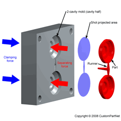
what is projected area ? projected area is area that one line with mold base parting line, for complete calculation, calculate the runner projected area and part projected area is more precision. see picture below to get the imagine og projected area

Clamping force calculator
below are clamping force calculator using java script, the script i get from http://www.custompartnet.com, with little modification so it's more suitable with blogger post page.
this picture below also have good visualization to explain projected area, clamping force and injection pressure

if you prefer see original calculator go to this webpage Clamping force calculator
but why i set safety factor 0.8, the result will more lower than without safety factor, in clamping force those formula is before correction for pressure drop and other, so the injection pressure always more lower than those manual calculation.
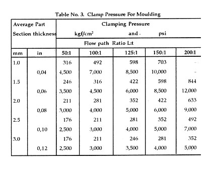
or we can use graph or table to define clamping pressure, like this one from niir.org

Injection molding machines are usually characterized by the tonnage of the clamping force that they provide. The clamping force, indicates the amount of force that the clamping unit can apply to the mold to keep it securely closed during the injection of the molten plastic, picture below shown injection machine from Nissei with type NEX80 (80 ton)
formula
the clamping force is proportional to the projected area of the moulding and runner, and must be opposed by the clamping force. although a proportion of the pressure produced by the injection cylinder is transmitted to the cavity, various losses occurring in the heating cylinder, nozzle and gate we can consider that force acts on the mold to make it open can be calculated from the following formula:
Force (lb.) = Pressure (lb/in2) x Projected Area (in2)
what is projected area ? projected area is area that one line with mold base parting line, for complete calculation, calculate the runner projected area and part projected area is more precision. see picture below to get the imagine og projected area

Clamping force calculator
below are clamping force calculator using java script, the script i get from http://www.custompartnet.com, with little modification so it's more suitable with blogger post page.
Clamping Force
this picture below also have good visualization to explain projected area, clamping force and injection pressure
if you prefer see original calculator go to this webpage Clamping force calculator
but why i set safety factor 0.8, the result will more lower than without safety factor, in clamping force those formula is before correction for pressure drop and other, so the injection pressure always more lower than those manual calculation.
or we can use graph or table to define clamping pressure, like this one from niir.org
Thursday, November 22, 2007
Top Plate, Stripper Plate,Sprue Bush and Runner Lock Pin Design
4:13 PM
3plate, Locating Ring, Mold Component, mold design, Mold part and construction, top plate
4 comments
at the picture below you will see a set of Top plate until stripper plate design related with runner flow, at this picture support pin exclude. the mold type in this picture is 3 plate type.
the runner system accommodates the molten plastic material that coming from barrel, and guide it into mold cavity, the dimension, configuration, shape, and system connection with mold cavity will affect filling process.

as see from that picture, red plate indicate isolated plate, it's doesn't matter you use isolated plate or not, but you must see more in injection machine, if it needed isolated plate give it. number 1 and 2 in black plate it's indicated top plate for number 1 and stripper plate for number 2, those picture shown 3 open mold type.
after injection, in ejection process stripper plate will open because puller bolt pull it( not include at those picture).
runner ejector set will needed to push runner, after ejection, but if you use arm robot or manual take the runner by hand operator it doesn't needed. runner ejector set always contains spring, those spring will push pin in ejector set and will push the runner.
runner lock pin function is to pull runner when ejection begin still in top plate, if runner adhere in stripper plate, the robots or operator will difficult to take the runner, because no ejection system for runner in stripper plate.
when design the runner system and ejection system for runner in 3 plate type of mold you should use those mold accessories.
the runner system accommodates the molten plastic material that coming from barrel, and guide it into mold cavity, the dimension, configuration, shape, and system connection with mold cavity will affect filling process.

as see from that picture, red plate indicate isolated plate, it's doesn't matter you use isolated plate or not, but you must see more in injection machine, if it needed isolated plate give it. number 1 and 2 in black plate it's indicated top plate for number 1 and stripper plate for number 2, those picture shown 3 open mold type.
after injection, in ejection process stripper plate will open because puller bolt pull it( not include at those picture).
runner ejector set will needed to push runner, after ejection, but if you use arm robot or manual take the runner by hand operator it doesn't needed. runner ejector set always contains spring, those spring will push pin in ejector set and will push the runner.
runner lock pin function is to pull runner when ejection begin still in top plate, if runner adhere in stripper plate, the robots or operator will difficult to take the runner, because no ejection system for runner in stripper plate.
when design the runner system and ejection system for runner in 3 plate type of mold you should use those mold accessories.
Sunday, November 11, 2007
Slider Design and Basic Construction
picture below show slider basic construction in Mold, various construction and litle part available in slider but the basic construction of slider is same, look picture below, sorry if this picture is too grainy, i'll make a new one.

the main part from those picture is mold plate, number 1 until 10 is shown the plate of mold
plate 1 is top plate
plate 2 is gate opener plate, retainer plate, and others name depend in fabrics
plate 3 is cavity plate
plate 4 is core plate
plate 5 is backing plate
plate 6 is support plate
plate 7 is ejector plate
plate 8 is ejector retainer plate
plate 9 is bottom plate
plate 10 is runner plate
and the slider part name are
g for angular pin, this pin always have certain degree, usually between 10-30, angular pin will transfer vertical movement to horizontal movement, others construction, angular pin not from the top but from bottom, this kind of construction is rare to use now.
h is slider core, when contact with angular pin, this part also the core from slider construction, at this part we can attach insert part that mold the shape of plastic.
i is slider locking block, we can depend in angular pin when mold closed, slider pin is too week, so the holder of pressure from inside mold during injection process is locking block.
k is slider lock plate, for non mass production you do not have to attach this part, but if the mold used in mass production, i suggest to use this part, because slider locking block and slider core always have friction, then when this part broken or got abrasive is will need expensive cost to repair it, so use lock plate is better, is cheaper.
l(L) is slider insert, this part which form the plastic product, it's attach in slider core

the main part from those picture is mold plate, number 1 until 10 is shown the plate of mold
plate 1 is top plate
plate 2 is gate opener plate, retainer plate, and others name depend in fabrics
plate 3 is cavity plate
plate 4 is core plate
plate 5 is backing plate
plate 6 is support plate
plate 7 is ejector plate
plate 8 is ejector retainer plate
plate 9 is bottom plate
plate 10 is runner plate
and the slider part name are
g for angular pin, this pin always have certain degree, usually between 10-30, angular pin will transfer vertical movement to horizontal movement, others construction, angular pin not from the top but from bottom, this kind of construction is rare to use now.
h is slider core, when contact with angular pin, this part also the core from slider construction, at this part we can attach insert part that mold the shape of plastic.
i is slider locking block, we can depend in angular pin when mold closed, slider pin is too week, so the holder of pressure from inside mold during injection process is locking block.
k is slider lock plate, for non mass production you do not have to attach this part, but if the mold used in mass production, i suggest to use this part, because slider locking block and slider core always have friction, then when this part broken or got abrasive is will need expensive cost to repair it, so use lock plate is better, is cheaper.
l(L) is slider insert, this part which form the plastic product, it's attach in slider core
Saturday, September 15, 2007
Coring uniform wall thickness
when design a mold then we find nonuniform wall thickness, we can make little graduation translation using core, of course if there was not function parts,
ordinary parts like not cosmetic parts, touching with others parts, sliding and etc, should we change by making insert in core or cavity side. look at picture below
when a parts have no uniform thickness after injection process, sink marks and unfill product like void will occurs,

Different wall thicknesses in the same component cause differential shrinkage which, depending on component rigidity, can lead to serious warpage and dimensional accuracy problems To attain uniform wall thickness, thick-walled areas of the moulding should be cored like picture above,
the best core for graduation translation and easier material flow is by make radius in every corner, beside flow more easier there will easy when machining process used,and no need EDM process so it's should cost down the price of product.
ordinary parts like not cosmetic parts, touching with others parts, sliding and etc, should we change by making insert in core or cavity side. look at picture below
when a parts have no uniform thickness after injection process, sink marks and unfill product like void will occurs,

Different wall thicknesses in the same component cause differential shrinkage which, depending on component rigidity, can lead to serious warpage and dimensional accuracy problems To attain uniform wall thickness, thick-walled areas of the moulding should be cored like picture above,
the best core for graduation translation and easier material flow is by make radius in every corner, beside flow more easier there will easy when machining process used,and no need EDM process so it's should cost down the price of product.
Thursday, September 13, 2007
Wall thickness in mold design
when design a product The basic wall of the part of the melt during injection, should be kept uniform, this important to prevent sink after injection.
even we use cooling after injection part well deform because shrinkage, at this time if wall thickness does not same part will warpage stress
they key is keep wall thickness part as uniform as posible