as we know clamping unit purpose is to keep mold closed against force when part injected with plastic material, because of that clamping force at least more than injection force, we can applied this clamp pressure both in injection machine with hydraulic or with mechanical toggle.
Injection molding machines are usually characterized by the tonnage of the clamping force that they provide. The clamping force, indicates the amount of force that the clamping unit can apply to the mold to keep it securely closed during the injection of the molten plastic, picture below shown injection machine from Nissei with type NEX80 (80 ton)

formula
the clamping force is proportional to the projected area of the moulding and runner, and must be opposed by the clamping force. although a proportion of the pressure produced by the injection cylinder is transmitted to the cavity, various losses occurring in the heating cylinder, nozzle and gate we can consider that force acts on the mold to make it open can be calculated from the following formula:
Force (lb.) = Pressure (lb/in2) x Projected Area (in2)
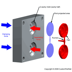
what is projected area ? projected area is area that one line with mold base parting line, for complete calculation, calculate the runner projected area and part projected area is more precision. see picture below to get the imagine og projected area

Clamping force calculator
below are clamping force calculator using java script, the script i get from http://www.custompartnet.com, with little modification so it's more suitable with blogger post page.
this picture below also have good visualization to explain projected area, clamping force and injection pressure

if you prefer see original calculator go to this webpage Clamping force calculator
but why i set safety factor 0.8, the result will more lower than without safety factor, in clamping force those formula is before correction for pressure drop and other, so the injection pressure always more lower than those manual calculation.
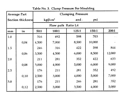
or we can use graph or table to define clamping pressure, like this one from niir.org

Injection molding machines are usually characterized by the tonnage of the clamping force that they provide. The clamping force, indicates the amount of force that the clamping unit can apply to the mold to keep it securely closed during the injection of the molten plastic, picture below shown injection machine from Nissei with type NEX80 (80 ton)

formula
the clamping force is proportional to the projected area of the moulding and runner, and must be opposed by the clamping force. although a proportion of the pressure produced by the injection cylinder is transmitted to the cavity, various losses occurring in the heating cylinder, nozzle and gate we can consider that force acts on the mold to make it open can be calculated from the following formula:
Force (lb.) = Pressure (lb/in2) x Projected Area (in2)
what is projected area ? projected area is area that one line with mold base parting line, for complete calculation, calculate the runner projected area and part projected area is more precision. see picture below to get the imagine og projected area

Clamping force calculator
below are clamping force calculator using java script, the script i get from http://www.custompartnet.com, with little modification so it's more suitable with blogger post page.
Clamping Force
this picture below also have good visualization to explain projected area, clamping force and injection pressure
if you prefer see original calculator go to this webpage Clamping force calculator
but why i set safety factor 0.8, the result will more lower than without safety factor, in clamping force those formula is before correction for pressure drop and other, so the injection pressure always more lower than those manual calculation.
or we can use graph or table to define clamping pressure, like this one from niir.org