Injection Mould Construction

A molding according to the function of each of its parts can be divided into four sections 1. Introductory part of the plastic nozzle into the cavity cavity 2. penunjuang system (support system) 3. demolding system 4. heat transfer system

Mold Base Standard Part

In the manufacture of injection mold, mold base is an integral part, mold maker can make your own mold base or buy a standard mold base, the system of the mold base can be adjusted with the construction standards required, both for the two plate and three plate, stripper plate ejectors, hot runner and mold base for a screw, when the entire standard mold base is not there to meet the new final step is to make a special mold base.

Injection Mould Classification

classification or types of mold injection very depend on what we need to make the plastic parts, because every parts have specific and unique design. when design molds we must see what the influencing factor like geometry, number of cavities, ejection principle, plastic material and shape of part.

Injection Mold Cooling

This section is the most important part of the overall mold cylcle time, because in one cycle time, the process of heat exchange to spend about 70-80% of the total cycle time, thus setting the optimal heat transfer system will greatly affect the quality and cycle time of a product.

Undercut System : Cam, Angular, Lift Cavity, Loose core

cavity and core, and its derivatives when there are undercut on product, design and construction of a good core cavity and in accordance with the requirement could increase the life of tooling itself, reduce material consumption, reduce dependence on maintenance inserts, and can reduce the cost of making the mold so the mold cost per products also declined.

Showing posts with label Mold Component. Show all posts

Tuesday, August 26, 2008

Pin Point Gate Construction

pin point gate is commonly used in 3 plate mold types, see explanation more about 3 plate more here, basically the pin point gate part is like picture below


those picture is pin point gate picture, to make gate like that we can buy pin point gate bush in mold manufacture company or we make it by EDM (electronic Discharge Machine) Process, the special EDM torch for Pin Point gate also available in mold part markets.
Pin Point gate Bush
picture below shown simple pin point gate bush,


the construction to assembly the pin point gate bush in mold is like picture below
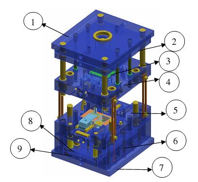
straight, without extended bush, picture below shown, locating ring, pin point gate bush, runner lock pin, runner, product and mold base plate (top plate, stripper plate and cavity plate)


some times, we need extended pin point gate bush, why when plastic material have high shear rate, we need to assembly extended bush, so from diameter gate until runner plastic material will easy to flow the cavity.
see the construction at picture below


here some good link of standard component of gate,
http://www.misumi-europe.com/www/lang/catmold_eng/nav/006/hl/007/menu/catalogues/fn/21/content.html

Monday, February 11, 2008

Basic Functions of Mold Base Parts

A mold plate is any plate required to built a complete mold, in all plate use for molds have the main requirements, they are :
1. Good corrosion resistant
2. Good Machinability.
3. Easy to clean
3. Good heat transfer.
4. Homogeneity of steel.
5. Easy ability.
6. Low Cost.

at picture below you can see 3 plate mold base type with closed position, basically 3 plate type and 2 plate type has some main plate, see explanation about mold construction type to understand more,


explanation below based on number at those picture
1. Fixed Clamping Plate or Top Plate
Holds The fixed side of the mold to attached at the fixed platen of the injection machine. at this plate will attach locating ring, eye bolt, and sprue bush.
2. Runner Stripper Plate
this plate only used in 3 plate molds type, the function is to cut resin from nozzle in top of sprue bush, and pull the runner by runner locking pin.
3. Fixed Mold Plate or Cavity plate.
use to hold cavity side of product, leader pin, support pin, Puller bolts, and Angular pin when slider attached.
4. Movable Cavity Plate or Cavity plate
it used to attach core side of product, return pin, leader bush and slider core if needed.
5. Back up Plate or Support plate
used to support cavity plate, attach the hole for return pin's spring, and cooling channel when in cavity plate can not make it.
6. Spacer Block
Mounted between the movable clamping plate (bottom plate) and the movable cavity plate to give space and allow the ejector plate to move when ejecting the
part. the required length of spacer block depend on ejector stroke that needed to eject product.
7.Ejector retainer plate
to hold the ejector, Z pin, shoulder bolts,and give space to ejector leader pin and support pillar.
8. Ejector Plate
Pushes the ejector pins and return pins, connected with ejector rods.
9. Movable Clamping Plate or Bottom plate
Holds The movable side of the mold like spacer block, support plate, cavity plate and ejector mechanism to the movable platen of the injection machine.


and look at picture below, shown 3 plate molds type in opening position, but at picture below, Bottom plate or movable clamping plate is number 7, number 8 is ejector retainer plate, and number 9 is ejector plate.


Thursday, November 22, 2007

Top Plate, Stripper Plate,Sprue Bush and Runner Lock Pin Design

at the picture below you will see a set of Top plate until stripper plate design related with runner flow, at this picture support pin exclude. the mold type in this picture is 3 plate type.

the runner system accommodates the molten plastic material that coming from barrel, and guide it into mold cavity, the dimension, configuration, shape, and system connection with mold cavity will affect filling process.


as see from that picture, red plate indicate isolated plate, it's doesn't matter you use isolated plate or not, but you must see more in injection machine, if it needed isolated plate give it. number 1 and 2 in black plate it's indicated top plate for number 1 and stripper plate for number 2, those picture shown 3 open mold type.
after injection, in ejection process stripper plate will open because puller bolt pull it( not include at those picture).

runner ejector set will needed to push runner, after ejection, but if you use arm robot or manual take the runner by hand operator it doesn't needed. runner ejector set always contains spring, those spring will push pin in ejector set and will push the runner.

runner lock pin function is to pull runner when ejection begin still in top plate, if runner adhere in stripper plate, the robots or operator will difficult to take the runner, because no ejection system for runner in stripper plate.

when design the runner system and ejection system for runner in 3 plate type of mold you should use those mold accessories.

Sunday, November 18, 2007

When we need slider parts in Mold Design

second previous post i have post about the slider parts and construction in complete mold base , then now i give a little brief when we need slider in mold design, basically we design mold from our customer, first is we must look the parts that we will make by plastic mold, look mare at the drawing so we can know about tolerance and critical point of parts, seconds is define the parting line, first parting line is between core and cavity parts, and after that if the parts have side form we must define slider parting line, look picture below


from those parts we know that we need slider parts, side hole and other shape that can not form by core and cavity became slider parts. below is picture in 3D modeling,look at the hole shape in side, those shape need slider part.


and how the construction of slider, more about construction mold you can see by clicking mold construction or molds parts in quick topic, basically here i give slider 3D modeling and parts name, those parts names i take from Misumi standard mold design


you can use this tutorial for education and others purpose but still write copyright from this site.

Monday, September 10, 2007

SPRUE BUSH and LOCATING RING

when you choose sprue bush, make sure you was know the diameter ball nozzle of plastics injection (SR) is less than diameter ball (SR - at picture below indicate by R)

if diameter R of Sprue bush to little than nozzle SR diameter, that will not good match or touching, if injection machine working plastic flash will out between nozzle and sprue

LOCATING RING

some mold designer usually use Locating ring to prevent unmatching nozzle of injection machine, before choose inside diameter of locating ring, we must know the outer diameter of nozzle that will touch with locating ring, at the picture below written in purple

Red color indicating flow of plastic material, from this picture we can take a conclusion that the picture is 2plate type of mold, look at picture there is no runner plate, and the gate type is side gate


Z pin Ejector

is used to make the runner ( RED COLOR) still adhere in core side when mold open and take the product, then Z pin will push the runner together with other ejectors