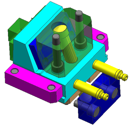
Injection Mould Construction

A molding according to the function of each of its parts can be divided into four sections 1. Introductory part of the plastic nozzle into the cavity cavity 2. penunjuang system (support system) 3. demolding system 4. heat transfer system

Mold Base Standard Part

In the manufacture of injection mold, mold base is an integral part, mold maker can make your own mold base or buy a standard mold base, the system of the mold base can be adjusted with the construction standards required, both for the two plate and three plate, stripper plate ejectors, hot runner and mold base for a screw, when the entire standard mold base is not there to meet the new final step is to make a special mold base.

Injection Mould Classification

classification or types of mold injection very depend on what we need to make the plastic parts, because every parts have specific and unique design. when design molds we must see what the influencing factor like geometry, number of cavities, ejection principle, plastic material and shape of part.

Injection Mold Cooling

This section is the most important part of the overall mold cylcle time, because in one cycle time, the process of heat exchange to spend about 70-80% of the total cycle time, thus setting the optimal heat transfer system will greatly affect the quality and cycle time of a product.

Undercut System : Cam, Angular, Lift Cavity, Loose core

cavity and core, and its derivatives when there are undercut on product, design and construction of a good core cavity and in accordance with the requirement could increase the life of tooling itself, reduce material consumption, reduce dependence on maintenance inserts, and can reduce the cost of making the mold so the mold cost per products also declined.

Saturday, October 2, 2010

Top 6 Injection Molding Company

it's difficult to list all company that provide any solution about injection machine, include manufacturer, injection molder, machine maker, and injection design, based on the survey is limited to friends and colleagues associated with the injection mold, which many ads appear on Google, and companies that contribute most in the book and seeing appear in the books of injection mold, here I will be showing 6 of the most famous course according to my own version, because I do not have complete data. assessment should be based on the type of machine made, proceeds, income per year, the number of employees, average employee welfare, customer satisfaction and how many problems that arise from the resulting product.
Injection Molding Handbook, 2nd Edition


1. HUSKY,
if you often read a book mold, of course, will easily recognize these companies from Canada,
Husky designs and manufactures the industry’s most comprehensive range of complete, integrated injection molding systems for a variety of key markets. Our systems include Hylectric, HyPET, HyPAC and HyCAP
    * Hylectric  – our base platform on which we've build a wide range of specialized systems for a variety of applications including closures, thinwall/IML, pails, and cutlery
    * HyPET – lightweight PET preforms
    * HyCAP – high output beverage closure manufacturing
    * HyPAC – high performance thinwall packaging


2.SUMITOMO DEMAG
Sumitomo (SHI) Demag is one of the leading manufacturers of plastic injection moulding machines anywhere in the world together with its Japanese parent group. More than 3,000 workers come up with and produce outstanding machines and solutions at 4 production locations in Germany, Japan and China.
 develop and manufacture a range of all-electric,hybrid and hydraulic injection moulding machines with clamping forces ranging from 180 kN to 40,000 kN.


3. ARBURG
is one of the leading global manufacturers of injection moulding machines. Robotic systems, complex production cells and other peripherals are also included in our product range.

4. NISSEI
This company is very famous in world injection machine, because kepresisianya especially for products with small tonnage, nissei producing machine with a capacity of 7 tons to 1500 tons, penjualanya many areas of Asia and America


5. DONGSHIN

Dongshin Hydraulics has continually striven to be one of the
premier manufacturers of injection molding machines world-wide through our continual investment in reserch and development-with 38 years of acquired technology and the closest co-operation with our customers.
since its establishment in 1960 the company was growing rapidly and could become the best performing companies in Korea in 2007, the marketing is a broad range ranging from southeast asia, korea, china to India and Africa.


6. JSW
As a leader in the industry, JSW provides a full line of injection molding machines, ranging from small to ultra-large models, which offer ease of operation, safety, and environment-friendly improvements such as energy- and space-saving features. Moreover, we offer technical support in line with customer needs, including consulting service and systems for factory automation. JSW has established a global network which covers the United States, Europe, and Asia

Tuesday, August 17, 2010

wall thickness and sink mark estimation

Uniform wall thickness in plastic part design is critical.Non-uniform wall thickness can cause serious warpage and dimensional control problems.One of the easiest ways to cure this problem is change the part geometry by adding ribs. The use of ribs is a practical way and economical means of increasing the structural strength of a part.  it is more economical to use ribs than increase wall thickness, But there are guidelines that govern adding ribs without causing sink marks or surface blemishes to your parts. in parts requiring good surface appearance, ribs should be avoided as sink marks on the opposite surface will surely appear.
The wall thicknesses of an injection-molded part generally range from 2 mm to 4 mm (0.080 inch to 0.160 inch). Thin wall injection molding can produce walls as thin as 0.5 mm (0.020 inch).
Rib thickness should be less than wall thickness. A rib thickness of 60% to 80% of nominal wall thickness is recommended. (plastics1.com)

using finite element software or relevant software for injection mold like, Mold flow, C-Mold, Etc, we can estimate the sink mark that will appear, picture below for example, with different rib we can see that sink mark result also different, first rib (from left) have 0.6 * thickness part, second rib thickness same with part thickness, 


Thick sections cool slower than thin sections. The thin section first solidifies, and the thick section is still not fully solidified. As the thick section cools, it shrinks and the material for the shrinkage comes only from the unsolidified areas, which are connected, to the already solidified thin section (efunda.com)

non uniform wall thickness also can cause voids and non-uniform shrinkage, for example in a sharp outside corner and a properly filleted inside corner could present problems due to the increased wall thickness at the corner. to prevent that we can add additional radius or shape like picture below 


How About Bosses?
Bosses are used for locating, mounting, and assembly purposes. There are boss design guidelines that must be followed to insure the highest quality in molded parts. Again, one of the main points to consider is nominal wall thickness. Too many times bosses are designed with thick wall sections that can affect the appearance of the plastic part and the final product. (plastic1.com)
As a rule, the outside diameter of a boss should be 2 to 3 times the hole diameter to ensure adequate strength. The same principles used in designing ribs pertain to designing bosses, that is, heavy sections should be avoided to prevent the formation of voids or sink marks and cycle time penalty.Less good design of bosses can lead to sink marks.

to prevent that, design the boss like picture below is preferred


Rule of thumb: the wall thickness around a boss design feature (t) should be 60% of the nominal part thickness (T) if that thickness is less than 1/8". If the nominal part thickness is greater than 1/8" the boss wall thickness should be 40% of the nominal wall
.Boss diameter, wall thickness, and height design parameters. While boss heights vary by design, the following guidelines will help avoid surface imperfections like sink marks and voids: the height of the boss should be no more than 2 1/2 times the diameter of the hole in the boss.


Monday, August 2, 2010

Locking Block With Angular Slider

What should you do when the slider design and found that the angular slider too long? There are many ways to change the design so that the angular length of the slider pins are still reasonable when compared to its diameter.in design between the angular diameter and length of the slider pins should be noted, the length of angular slider pins that are too long can lead to easily broken when the mass production run, especially if the small angular diameter, the way the installation is also a concern to be easy in the process of repair when damage occurs.
the above  picture, I took when designing the angular pin slider, when the client wants the angular pin slider must exist, and based on the calculation of stroke, it turns out the angular pin length is too long, surely this is dangerous and i should change the design concept.
other than dangerous, the above design concept is also difficult in maintenance because if the angular pin broke the mold base must be dropped from the injection machine, disassembly the mold then can be replaced, this is because the angular pin must be in pairs from the top plate embedded in the cavity

Locking Block With Angular Slider
This design concept in addition to saving space, saving the long angular slider also has the advantage of easy installation and maintenance, although the angular pin mold was broken when used for production, the mold does not need to send down from the injection machine to replace it. look at picture below


on the design concept above, I only use one bolt to tighten to the cavity plate, simple but I'm sure I could save the angular length of approximately half of the angular slider before. The above concept also facilitates the repair process.


The second alternative was similar, but the difference is the number of bolts are used and how big a part of the locking block affixed to the cavity plate, the first altenative collar only are plugged into the cavity plate, and the bolts, of course, only part that holds the slider in the section just the collar. A second alternative is different from all bagianya embedded in the plate cavity.
I chose the second alternative concept, the concept was made 3D and 2D drafting calculations based on a stroke, for details, under the following 3D image is the result of the 3D design of the second alternative.


Saturday, June 26, 2010

slider construction : cam or angular pin

posts related to construction and part-bagianya slider has been my post, about the cooling on the slider, the basic construction for the slider, the slider and the main part, please see previous post to learn the basic construction and when we should use the slider, This post will discuss about when we need to use of the slider that use angular pin or just cam slider, what advantages and disadvantages of both types of construction such slider. 
ANGULAR PIN
basically, the type of construction of the slider based on how to pull out the core slider is divided into three types, first use the angular pin,using the force of the angular pin at a certain angle, the slider block would be pull out, the second is a cam slider, just use the thrust of the spring and stopper on the slider, and calculating a stroke, cam slider allows you to easily pull the slider core, the third is the use of hydraulic or pneumatic system to pull the slider core, specifically for the third way is needed so that movements of individual controls in accordance when the slider open mold and mold close.picture below shows slider with angular pin system.


 picture above shown standard complete construction for slider, it's include cooling plug, stopper (blue color), adjustment plate between locking block and slider core(blue), guide rel (pink) etc. angular pin system very common use in slider system, Angular sometimes do not have a round pin, shape the box is also commonly used, actually used the same angle, both will be used by considering the strength, structure, mold, and the available space.
The advantage is the use of angular pins can be used for parts that have undercut short or long, easy to maintain when the angular broken, just enough to change the angular pin. inexpensive in manufacture, and can be used for long-stroke slider to medium, the angular pin length has not touched bottom plate. 


for instance,look at picture above if undercut wide for most of the parts, use the slider two pins with a diameter sufficient, then you will get a strong slider construction and safe.

CAM SLIDER
while the slider does not require angular cam pin, the cam slider there are several types of commonly used, the clamp type,  two angle type, cam units type and one direction cam. because in using the cam to take calculation of a stroke is used, why?? it's to prevent slider core not be separated from the locking block, and the strength of the spring, so that true core slider can move and hit the stopper. cam slider can only be used for minor stroke (0.5 mm-5mm), small undercut, and not too wide undercut form.

a benefit is a cam slider can be used for high cycle time, mold construction, saving space, and easy assembly.

whereas the less than the limited form that can be undercut in the form, was difficult in the manufacture and maintenance. 


Sunday, May 9, 2010

Troubleshooting warpage on injection molds

Warping, Part Distortion is shows up as parts being bowed, warped, bent or twisted beyond the normal specification outlined on the drawing.Warpage occurs when there are variations of internal stresses in the material caused by a variation in shrinkage. Warped parts may not be functional or visually acceptable.

Main Causes
1.Non-uniform cooling
Temperature differences from one side of the mold to the other can lead to layers freezing and shrinking at different times and generating internal stresses.   Temperature differences from one side of the mold to the other (differential cooling).
 2. Inconsistent shrinkage or non uniform stress due excessive orientation of shringkage.Variations in the magnitude of shrinkage in directions parallel and perpendicular to the material orientation direction (orientation effects). 
Process conditions variations such as inconsistent packing and varying mold and melt temperatures;   low pressure, mold temperature of ejection too hot,  Material variations such as property variations, varying moisture content, inconsistent melt and pigmentation; 

Possible Solutions

  • Adjust melt Temperature (increase to relieve molded-in stress, decrease to avoid overpacking). stress, decrease to avoid over packing). stress, decrease to avoid over packing).
  • Check gates for proper location and adequate size.
  • Check mold knockout mechanism for proper design and operation.
  • Equalize/balance mold temperature of both halves.
  • Increase injection-hold.
  • Increase mold cooling time.
  • Perhaps one of the easiest things to alter is the temperature of the coolant. It may be useful to run two additional Cool analyses with the coolant inlet temperatures at say plus and minus 5°C with respect to the original inlet temperature used
  • Relocate gates on or as near as possible to thick sections.
  • Try increasing or decreasing injection pressure.
  • Use thinner wall sections with ribs. Thicken only those wall sections that require extra material for structural stability and that cannot be strengthened using another method.   
  • Change the part geometry. Add features such as stiffening ribs to the design. Change the part design to avoid thick sections and reduce the thickness of any features that intersect with the main surface.  

Wednesday, March 24, 2010

Troubleshooting weld lines and meld lines on injection molds

In manufacturing, the Weld line or Knit line or Meld line is the line where two flow fronts meet when there is the inability of two or more flow fronts to "knit" together, or "weld", during the molding process. These lines occurs usually around holes or obstructions and cause locally weak areas in the molded part.

A weld or meld line is a weakness or visible flaw created when two or more flow paths meet during the filling process. Weld lines can be caused by material flowing around holes or inserts in the part, multiple injection gates or variable wall thickness where hesitation or "race tracking" can occur. If the different flow fronts have cooled before meeting, they don't interfuse well and can cause a weakness in the molded part. A line, notch and/or color change can appear.

What Caused Weld or Melt Line?
A meld line occurs when two moving melt fronts converge and flow parallel to each other. Weld and meld lines are generally caused by holes or inserts in the part, multiple gates, variable wall thickness or hesitation and race track effects.

explanation from http://www.imtechdesign.com/ give brief reason why and when weld line, and melt line will occurs.

a meeting angle, smaller than 135º produces a weld line; greater than 135º, a meld line. Note that the weld line surface mark disappears when the meeting angle reaches 120º to 150º. Normally, weld lines are considered to be of lower quality than meld lines, since relatively less molecular diffusion occurs across a weld line after it is formed. However, there is always an exception to the rule and some materials by nature tend to exhibit more visible weld lines irrespective of the angle. In addition many fillers and additives also highlight weld & meld lines. Glass fibres and metallic pigments are good examples.

Weld lines, melt lines or Knit lines could be caused by different causes:

- Low temperature of molding machine barrel
- Inadequate back pressure
- Injection pressure or injection speed is too low
- Low mold temperature
- Small injection gates and/or runners
- Improper location of injection gate
- Excessive gate land length
- Improper flow rate of injected materials
- Inconsistent process cycle

Weld Line and Physical Properties
A study of the effect that weld lines and orientation have on physical properties of molded parts was undertaken to establish general guidelines for use in part design. an experiment by dupont show that between polymer orientation, Weld Lines. And tensile Strength have Relationship, see graph below.


These results show the importance of gate location and the need for the product
designer to coordinate his efforts with the tool builder. The gate should be located
both to avoid weld lines in high stress areas and to take full advantage of glass fiber reinforcement. Techniques the designer might use to reduce stress level at a weld line include increasing the wall thickness or adding ribs.

Solution
- This can be done by changing the polymer injection location or altering wall thicknesses to set up a different fill time.
- increasing mold temperature, melt temperature, injection rate and pressure.
- Increased mold venting or addition of flow tabs also can help turn a bad weld into
a good weld
- Change the gate positions.
- Change the part thickness.
- Optimize runner system design. Reduce runner dimensions and maintain the same flow rate to use shear heating to increase the melt temperature at the flow front
- Instead, it often helps to increase the injection velocity, decrease the fill time, and increase the shear rate, which can lower the viscosity of the polymer during fill and thereby allow for better chain entanglement and better packing. Increasing pack or hold pressure also helps, as well as having longer pack and hold times. Increasing pack or hold pressure helps to eliminate low-pressure conditions at the weld line. Another tactic to promote more chain entangling at the weld line is to raise the mold temperature 10° C (20° F).