Injection Mould Construction

A molding according to the function of each of its parts can be divided into four sections 1. Introductory part of the plastic nozzle into the cavity cavity 2. penunjuang system (support system) 3. demolding system 4. heat transfer system

Mold Base Standard Part

In the manufacture of injection mold, mold base is an integral part, mold maker can make your own mold base or buy a standard mold base, the system of the mold base can be adjusted with the construction standards required, both for the two plate and three plate, stripper plate ejectors, hot runner and mold base for a screw, when the entire standard mold base is not there to meet the new final step is to make a special mold base.

Injection Mould Classification

classification or types of mold injection very depend on what we need to make the plastic parts, because every parts have specific and unique design. when design molds we must see what the influencing factor like geometry, number of cavities, ejection principle, plastic material and shape of part.

Injection Mold Cooling

This section is the most important part of the overall mold cylcle time, because in one cycle time, the process of heat exchange to spend about 70-80% of the total cycle time, thus setting the optimal heat transfer system will greatly affect the quality and cycle time of a product.

Undercut System : Cam, Angular, Lift Cavity, Loose core

cavity and core, and its derivatives when there are undercut on product, design and construction of a good core cavity and in accordance with the requirement could increase the life of tooling itself, reduce material consumption, reduce dependence on maintenance inserts, and can reduce the cost of making the mold so the mold cost per products also declined.

Friday, February 10, 2012

Injection Mould Venting System, a little part of design that have big effect on part quality

venting is a small part of the mold design, on the design process also requires a very short time, perhaps only 10% or less of the total time required in designing.sometimes is frequently neglected until molding trials indicate mold inadequacies related to venting. if we understand the purpose and function of vents, it's can assists mold designer to design where clearly additional vents required.

when the cavity space injected by plastic material, automatically empty space on the cavity will be filled with plastic material, the air in the cavity will be shifted to another place, what would happen if the air can not move, the air will experience a high pressure , so the temperature rises even higher, resulting in plastic that fills the cavity will be burning, the defect is called a burn, because of the importance of venting a lot of products that fail due to not properly inject the gas vent, especially for products that have a rib that thin and tall, as compared to thick products.


source : Plastic Today


The main function of the venting is
A. compressed air release
when compressed air is not expelled from the cavity, the plastic flow is inhibited, the result will be formed on a short shot of the product
2. compressed air will produce a gas with high temperature and burn the plastic around it, resulting in a defect burn marks, the product looks like a burn, this will greatly affect the look of the product.
3. when the gas mixed with plastic, the plastic will generate an uneven structure, which will reduce the strength of the product / mold parts produced, stress concentration also common in this region, which occurs due to the plastic notch.


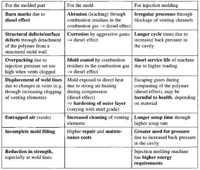
for more detail about effect of adequate of venting on injection mold, please see on picture below


part of venting, can divide on 2 section, land and groove, land is always contact with plastic melt, it's deep about 0.01 mm until 0.02 mm, depend on viscosity of material, relief of vent or gas land is about 1 mm until 2mm, but you must remember for rubber all the number above can't applied, gas vent on rubber material is very special, because rubber has low viscosity.
when designing the gas vent / venting on injection mould, make sure that all of the groove must have exhaust groove that connect to atsmosfer.

Monday, November 21, 2011

collapsible core for demolding/ejection system of internal screw undercut

one common way used in the ejection system for an internal screw is used collabsible undercut core, which requires collabsible core product generally has the undercut on the inside, for example an internal screw, pipe fittings, elbow pipe, use collabsibe core is not only on the core course , undercut the slider is also often used collabsible cores.
video below gives a simple explanation of how Collapsible cores working

http://www.die-moldtool.com/

Main Component
The three units are a Collapsible Core, center pin, and a positive collapse sleeve.

cenTer pin
The Center Pin serves to expand the segments of the Collapsible Core to their molding position and holds them at this diameter. A hole is provided inside the pin for cooling. The center pin is manufactured of a high alloy Type D-6 steel hardened to 60 to 65 Rockwell C or use SKH 51, SKD 11. Refer to the pin grinding instructions for machining directions. In use the pin must incorporate two design features. The pin must protrude beyond the face of the collapsing core segments by certain amounts. This protrusion keeps material from flowing under the face of the collapsing segments to ensure they properly collapse. A radius must be applied to the outside corner at the front of the center pin. The sharp edge resulting from cutting the pin to length will gall and subsequently destroy the inside surfaces of the collapsing core segments
collapsible core
The Collapsible Core is manufactured from A.I.S.I. Type A-2 steel hardened to 51 to 57 Rockwell C. It is designed to collapse independently when the center pin is withdrawn. The fit between segments is controlled to permit flash free molding. The location of the core on its pin is critical. The distance between the back of the core flange and the front of the center pin flange (Head Space) is critical and must be maintained.
If the Head Space (1.938 ±.005 on a CC 202 PC) is not maintained, unsatisfactory operation will result, or the core may be permanently damaged.
posiTive collapse sleeve
The Positive Collapse Sleeve (PC sleeve) is designed to function when the Collapsible Core fails to collapse independently upon withdrawal of the center pin. In normal operation, the PC sleeve is not functioning. It is essential to have such a unit for maximum safety and reliability in automatic and semi-automatic operation. Under no circumstances should a mold be placed into automatic operation without the use of the PC sleeve.


picture above shown collapsible core and the component, detail explanation about CC we can find it in DME standard part http://www.dme.net/dme/resources/FAQs/collapse_cores.html

Wednesday, June 29, 2011

Runner Design in Injection Mold,


in designing the runner, first-time we must consider items that affecting  runnersize, some of which
- Volume of part, the greater the volume takes a larger diameter runners anyway.
- Weight of part, the heavier parts, it takes a larger diameter runners.
- Plastic materials, plastic materials with low viscosity, aqueous requires a smallerdiameter runner.
- Wall thickness, the thicker the greater the diameter of the runner is needed.
- Length of flow path, the longer it takes the flow of large diameter runner.


picture above shown some factor that we must consider before choosing right diameter of runner, 

Cross Section Area
various cross section area use on the market, It depends on the heat loss, machining requirement, but the most popular cross section area are circular, parabolic and trapezoid section area, picture below shows three
Diameter
to determine the diameter, based on the type of material and wall thickness, the following chart can help, for similar materials PP, PA, POM, PC, PE can use the following graph, first select the appropriate thick wall thickness and look heavy parts, and then pull the line down, the approximate diameter required will be obtained


Monday, March 7, 2011

Lifting bolts hole design in injection mold

Plate transfer process occurs during the machining and assembly of mold, both for the cavity and mold base plate, especially for the plate with a weight greater than 20 kg, threaded hole necessary to facilitate the transfer process. cause may be in a mold plate having a various of machining processes with different types of machines. Base on position of hole the type of lifting bolts can divided became two, perpendicular to face, and parallel with face of plate.
perpendicular to face
beside transfer process, lifting bolts also important for lift out cavity insert from mold base, flat wide plate usually use magnet to lift from one machine to another machine or station, but if shape of plate doesn’t flat it need bolts hole to attach eye bolts, then use crane that connected to eye bolts for lifting the mold base plate or cavity plate.


Parallel with mold face.
Especially for mold base, this hole must available because transfer mold base usually use eye bolt that connected to crane, for mold base plate that use horizontal machining also use this hole to connected with crane, picture below shown mold base with metric bolt hole and eye bolts ready for transfer with crane


Monday, February 7, 2011

runner components of injection mold

Runner components between the two mold plate and three plate mold because there are different functions of these components, but there are several components that can be used in general without looking at the type of mold construction.


1.Runner lock pin
The main function of the runner lock pin (RLP) is an pulling runner so
the gate can be disconnected/cut from the product, RLP fitted with a straight gate position, the head planted on the top plate, while in the body mounted on the cavity plate (3) up to the top
plate (1). RLP does not move during the injection process lasts, mold base plate
moves accordance with the mold opening sequence, the tip of the runner lock pin is the part that greatly affects the success or failure of the gate runner cutting process. Greater the undercut which is the stronger the ability of RLP to attract runners from the gate, the type of plastic material also influenced for selection of RLP.
2.RLP Lock
RLP lock have function to maintain RLP order not to loose from its position, there are various ways to lock them RLP
* closed with a locating ring or sprue bush or heat insulation board.
* using a plate
* use a screw plug
3. Bushing RLP
high cycle time mold or need durability are advised to use the bushing,the benefits include easy maintenance of RLP, more resistant to wear due to friction so it's can avoid direct contact between RLP and mold plate that can caused wears, this method will shorten maintenance time.
4. Ejector runner
Only used if the runners stuck on the stripper plate mold base or stuck on the cavity mold bases, the use of the runner ejector can help the runner release from the place that was not supposed to stick. Other components are collar to the head of RLP, and change flow components

Wednesday, December 22, 2010

using mold base become locking block of slider unit

moldbase sometimes can be used for the locking block on the slider unit, this is basedon several reasons, for example, to reduce cost, by reducing the insert locking block, the other reason is required surface area for the locking block.


illustration picture above shows the angular pins are bolted to the mold base and the mold base made pocket instead of locking block,

to keep the process easy to do maintenance, should be installed oil slide plate, so when it can wear easily replaced without the need to change their plate slider block.
This model is widely used for large parts and molds with a tonnage greater than 350 tons, other advantage is the size of the mold base to be more compact and small, so the cost for the mold base can also be reduced, and if the size is smaller base can mold into tonnase also smaller