Injection Mould Construction

A molding according to the function of each of its parts can be divided into four sections 1. Introductory part of the plastic nozzle into the cavity cavity 2. penunjuang system (support system) 3. demolding system 4. heat transfer system

Mold Base Standard Part

In the manufacture of injection mold, mold base is an integral part, mold maker can make your own mold base or buy a standard mold base, the system of the mold base can be adjusted with the construction standards required, both for the two plate and three plate, stripper plate ejectors, hot runner and mold base for a screw, when the entire standard mold base is not there to meet the new final step is to make a special mold base.

Injection Mould Classification

classification or types of mold injection very depend on what we need to make the plastic parts, because every parts have specific and unique design. when design molds we must see what the influencing factor like geometry, number of cavities, ejection principle, plastic material and shape of part.

Injection Mold Cooling

This section is the most important part of the overall mold cylcle time, because in one cycle time, the process of heat exchange to spend about 70-80% of the total cycle time, thus setting the optimal heat transfer system will greatly affect the quality and cycle time of a product.

Undercut System : Cam, Angular, Lift Cavity, Loose core

cavity and core, and its derivatives when there are undercut on product, design and construction of a good core cavity and in accordance with the requirement could increase the life of tooling itself, reduce material consumption, reduce dependence on maintenance inserts, and can reduce the cost of making the mold so the mold cost per products also declined.

Saturday, February 9, 2008

Paralel and series Cooling methode at flat type plate of Mold Base

almost mold designer know that cooling is biggest part that effect cycle time of injection mold, a good design in cooling will make heat exchange between resin after injected and mold will reduce cycle time and give good product.
at flat type of mold base plate like stripper (Plate number2) plate between top plate and cavity plate, top plate it self, and support plate after core plate, at the top plate cooling not always used, it very depend on resin type,and product shape.
the picture below shown some flat mold base that we can use parallel or series cooling methods


How about core and cavity of Mold base ?


we can use both type of cooling series and parallel when design cooling at core and cavity plate, but you must careful place the cooling, because beside cavity molds it self, they are ejector at the core plate then sprue and runner system at cavity plate. the construction and how to connecting cooling at mold plate with cavity mold cooling will discuss later.

Parallel Cooling Channel
picture below shown parallel cooling channels concept


basic mold base cooling have four parts, they are :
1. Main Cooling pipe
commonly cooling pipe make by drilling using bore,the longer drilled hole, it recommended have length about 6 mm if using long nipple joint to connect with outer tube, if using nipple or inner joint plug each cooling pipe minimum have 12 mm.
2. stopper plugs, like at slider cooling and cavity cooling stopper plugs is prevent water or oil coolant flow to undesirable way.
3. Inner stopper plugs, the function is same as stopper plugs, but assembly methods and location is different, it assembled at inner of cooling pipe.

parallel cooling channels are drilled straight trough supply manifold cooling pipe, due the parallel design flow characteristics, the flow rate along various cooling will different, because each cooling pipe have their own flow resistance. as a results, cooling of the mold will not uniform. so it's clear that parallel circuit of cooling in molds are very poor flow rates.

Series Cooling
picture below shown basic series cooling construction and methods


the parts is same with parallel cooling type, but the construction is different, at the series cooling channel types, it connected in single loop from the coolant inlet until its outlet, we can configure the flow by adjust the inner stopper plug type.
when design it is recommended to use same size of diameter cooling, because it's can maintain the turbulent flow, turbulent flow enables heat to be transferred more effectively.

Long and Shorts Nipple joint plug Assembly methods

considering mold base material strength,closer distance between two nipple plug type are not advisable, look at picture below

assembly between long type and shorts type is different, by using long type minimum length from both side is 6 mm, except for little diameter hole, less then 5 mm, smaller length spacing my be acceptable.
Short nipple joint types almost assembly in inner mold base, because of that minimum length space is 12,5 mm, although 10 mm my acceptable but will difficult to assembly it using hand.

Sunday, January 27, 2008

Cavity mold cooling construction design

In commonly mold designer know that Cooling conditions affect cycle time, part dimensions, surface finish, and warpage. but some junior mold designer still confuse to make layout and construction of cooling in mold.

before this posting, i havepost about cooling construction in slider, beside slider mold cavity also important to fill cooling, why because almost product 70-80 % is molded shape in mold cavity.

picture above shown core side of cavity mold, the basic construction is
1. Plug (Plug is for prevent water flow out from desire flow layout)
2. cooling pipe (as those picture cooling pipe doesn't shown, almost cavity cooling pipe processing using jig bor to make a long hole that becoming cooling pipe)
3. In / Out Hole, it's hole also make using jig bore. this hole will attach in cavity plat that will match with cooling layout in mold base.
orange color indicate product insert hole shape.

here i post basic construction in single cavity, see picture below to learn more

picture above is shown flow of cooling process of cavity mold from top view.
then which hole water flow in and flow out, see picture below

at this wireframe method picture, we should make hole at bottom side of core to connected cavity and cooling layout of mold base.

Tips Design Cooling pipe for cavity
1. make sure side of cooling pipe have enough length from insert, minimum 3 cm
2. choose a good diameter for the hole, like 6 cm, 8 cm, or 10 cm.
3. when injection proses begin make sure using calculation so you have turbulent flow in cooling pipe.
4. make the pipe more long is useful for make turbulent flow.


then how the layout and construction of cooling in mold base ?
just wait for new post

Thursday, January 24, 2008

Mold Cooling Design at Slider

Why mold need cooling ? as we know that cooling conditions affect cycle time, part dimensions, surface finish, and warpage, Mold cooling time is the biggest contributor to the overall cycle time, it could be as two-thirds or 70-80% of total cycle time.

from those reason design an efficient cooling circuit can reduces the cooling time, beside that uniform cooling improve part quality by reducing residual stress, stability of heat transfer, and accuracies of part after cooled.

Why Slider Need Cooling?
Some product have long dimension that need slider, to prevent warpage, residual stress, and stability of shrinkage behavior, for that reason slider need cooling.

Mold Cooling Construction

picture below shown cooling construction at slider insert from top side.


annotation number at picture upper indicate part of slider, they are
1. Plug
2. Slider Insert
3. Cooling Pipe
4. Guide Rel of slider core
5. Locking Block slider
6. Long Nipple

Pipe with blue color indicate flow of water when cooling process working. number 1 part (Plug) prevent water flow to side of slider inserts.
When design nipple,make sure that nipple is long enough to reach outer side of mold base.

to get understand more look at picture below, at this picture still shown cooling at slider from left side.


additional number of slider parts are
7. slider core (this part is one of slider main part, where slider insert attached)
8. Angular slider ( the main function of angular is change the moving 90 degree, so slider can move)

Thursday, January 10, 2008

Plastic Processing Methode Types

Today, they are various plastic processing method available in industrial process, from the method of processing plastic we can divided into two big methods they are :


1. Molding Methode
this method usually use mold to melt the plastic, deformed with applied pressure and the product shape will same as the mold shape.
Various molding type method can be divided as
Extrusion Molding Method
this process can produce along product with fixed cross-sectional profile such as wire and cable coating, plastic tube for printer ink, some hollow profile and various solid profile. the material is pallet or plastic chips that are usually dried in a hopper before going to the feed screw. to process extrusion method used injection machine, The plastic heated at barrel to molten state then forced through a plastic mold die that is in desired shape. look at picture below to learn more about extrusion mold.


Injection Mold
Injection molding involves taking plastic in the form of pellets or granules and heating this material until a melt is obtained. Molten plastic is injected at high pressure into a mold, which is the inverse of the product's shape then it is allowed to cooling into the desired shape. The mold is then opened and the part is ejected, at which time the cycle is repeated. you should learn about various injection molds type at mold construction post
injection mold method have various kind of techniques like Thermoplastic Foam Injection Molding, Multi injection mold (sandwich mold, bi injection mold) gas assist injection molds and other, basic injection machine for injection mold you can see at picture below

to learn more about injection mold you should open introduction of injection molds post
Blow Molding Process
A thermoplastic resin is heated to a molten state It is then extruded through a die head to form a hollow tube called a parison. The parison is dropped between two mold halves, which close around it, the concept of blow mold you can see at picture below


we can divided blow mold four types as :
* Extrusion blow molding
* Injection blow molding
* Stretch blow molding
* Reheat and blow molding.
the picture above shown Stretch blow mold type, you should see more at Blow Mold Posting

Compression Molds
Compression molding is a method of molding in which the plastic, generally preheated, is first placed in an open, heated mold cavity, they are four step in compression molds they are loaded charge, charge compressed, cured the charge and ejecting process of product. the main construction is Punch (cavity side), core molds and ejection system.


Reaction Injection Molding (RIM)
the concept of RIM is Two reactant liquids are heated and brought together under high pressure. one example process is polyurethane RIM, At the heart of the polyurethane RIM process is a chemical reaction between the two liquid components, which are held in separate, temperature-controlled feed tanks equipped with agitators. From these tanks, the isocyanate and polyol feed through supply lines to metering units that precisely meter both components, at high pressure, to a mixhead device (http://www.rimmolding.com/rim/index.html), look at picture below, those picture shown two chemical reaction process mold isocyanete (blue tank) and polyol (red tank) .
the advantages of RIM is Strong, flexible, lightweight parts which can easily be painted. Quick cycle times compared to typical vacuum cast materials, the disadvantage is slow cycle time because must mixed before formed by mold.
Transfer Mold
transfer Mold or resin transfer mold (RTM)
like compression molding, is a process where the amount of molding material (usually a thermoset plastic) is measured and inserted before the molding takes place. The molding material is preheated and loaded into a chamber known as the pot. A plunger is then used to force the material from the pot through channels known as a sprue and runner system into the mold cavities. The mold remains closed as the material is inserted and is opened to release the part from the sprue and runner. The mold walls are heated to a temperature above the melting point of the mold material; this allows a faster flow of material through the cavities.


Thermoforming
is a manufacturing process for thermoplastic sheet or film by Heating a thermoplastic sheet and using a vacuum to pull the sheet over perforated mold. the product of this method is Fast food containers, advertising signs, panels for shower stalls


Pultrusion
Pultrusion is a continuous process of manufacturing of composite materials with constant cross-section whereby reinforcing fibers are pulled through a resin, possibly followed by a separate preforming system, and into a heated die, where the resin undergoes polymerization. Many resin types may be used in pultrusion including polyester, polyurethane, vinylester and epoxy.(Wikipedia)


2. Casting Mold
Casting is a manufacturing process by which a liquid plastic introduced into a mould, allowed to solidify within the mould, this characteristic of this molds is filling a molds by gravity, this kind type of casting molds are :
Liquid resins (epoxy)
Hot melted plastic poured into a casting (nylon)
Slush casting for thin walled products (snow boots, gloves, toys)
Wet spinning -fibers formed by spinning the solution through multi-hole dies
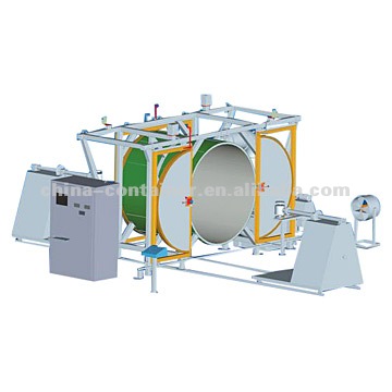
Rotational Mold
Rotational molding or moulding is a versatile process for creating many kinds of mostly hollow plastic Parts. The phrase is often shortened to rotomolding or rotomoulding.
molding of large products such as storage tanks and containers,
cPrnpIex toys, mannequins (display figures), etc., is achieved using rotational
molding. Lately, there are more and more applications for this technology.
.

Friday, December 21, 2007

Construction Injection Molds Classification

classification or types of mold injection very depend on what we need to make the plastic parts, because every parts have specific and unique design. when design molds we must see what the influencing factor like geometry, number of cavities, ejection principle, plastic material and shape of parts.

The basic classification of mold based on construction shown on picture below


1. Standard Molds
the standard mold is the most simple design, basically the standard molds is same as two plate molds construction, they divided in two side : cavity side and core side, cavity side is the side that construct to flowing plastic material from nozzle to cavity parts, basically they consist of sprue, runner.

core side construct to make shape for core, demolding system and ejection system, at this side we design ejection system.
standard mold have one parting line, and have one opening direction. this type of mold use in all kinds of plastic parts that doesn't have undercut, inner and outer screw.
Light brown color little and straight in ejection system is shown ejector pin.


2. Slide mold

development from this mold type is the used slider parts in various molds types, basic slide mold is transfer horizontal movement of mold to vertical movement, this types of molds is used to make parts with undercut, you should see more at the post when we need slider for learn more.


3. Three plate molds
basically three plate molds has two parting line, and floating plate, floating plate support by support pin, Since the mold has two parting planes, the runner system can be located on one side of floating plate or make special plate that attach in floating plate, we called runner plate, see post about runner plate. Three plate molds are used because of their flexibility in gating location. this types of molds is flexible even use in multiple cavity.

note : floating plate also called cavity plate or plate number 3, to know more the different between two plate mold and three plate mold see the posting about Basic and Types Molds Construction

4. Split Cavity Mold
basically the split cavity is same as 2 plate standard mold, but the cavity have split block to make undercut product or external threads.


this type of mold use when the slider is not enough to make the undercut or the threads. the disadvantages of this mold is when use for little parts, the construction will difficult.


5. Mold With Screw Device

this mold special to make thread forming, the core can be rotate when demolding process, both internal or external threads can be forming by this type mold.


from those picture we can see that they have gear device, the gear will rotate when form thread.


6. Stripper Ejector Mold
this type of mold have special purpose to make a cup shape without undercut, stripper ejector will make ejection more easy, same movement and power at the product and without a lot of marks in product


Molds with complex and difficult design can be integrated or combined one to the others mold type.

Saturday, December 15, 2007

Introduction to Mold Engineering of Thermoplastic

most electrical, and home appliances made from plastic, one of technology to make plastic product is using mold, specially injection mold of thermoplastic, basically when thermoplastic material heated, they will change of state, thermoplastic material will become soft, melt and flowable, when cooled again, they become solid again.

What is Injection Mold ?

there are some definition of injection mold

is a manufacturing technique for making parts from both thermoplastic and thermosetting plastic materials in production (wikipedia.com)

A manufacturing process for forming objects, as of plastic or metal, by heating the molding material to a fluid state and injecting it into a mold.(www.answer.com)

Herbert Ress, 2002 : an injection mold is arrangement, in one assembly a number of cavity spaces built to shape of the desired product, with the purpose of producing plastic parts in large number

this blog define injection mold is manufacturing process to make plastic product that have cavity spaces to shape the product by heating and injection pressure.

Types of Injection Molds
based on how injection mold would be processed wikipedia.org devide injection mold as 7 types until now, they are
1. Reaction injection molding
2. Liquid injection molding
3. Gas assist injection molding
4. Co-injection molding
5. 2-Shot Injection Molding
6. Fusible core injection molding
7. Rapid injection molding

based on type of opening method and runner system, The DIN ISO standard 12165, "Components for Compression, Injection, and Compression-Injection Molds" classifies molds on the basis of the following criteria:
1. standard molds (two-plate molds)
2. split-cavity molds (split-follower molds) stripper plate molds
3. three-plate molds
4. stack molds
5. hot runner molds

depending on material to be injected classifies as :
1.thermoplastic injection molds
2.elastomer molds
3.thermoset molds
4.structural foam molds

picture below shown 3 plate mold type with cold runner system and ejection system
click the picture to enlarge


closed Condition
picture below shown 3 Plate Molds Types in 3D design, in closed position with support pin, puller bolts, leader pin or positioning pin.


you can also learn more about basic pin construction at post about pin in molds
Opening Condition
then the construction molds of 3 plate type when opening is like picture below

picture below is shown three plate condition when open


we also can learning more about ppening Sequence, why and how the molds open, and explaining each molds opening step or sequence at post about opening construction

those opening sequence is just for 3 plate type, 2 plate type is more easy becouse just have one opening parting line.