Injection Mould Construction

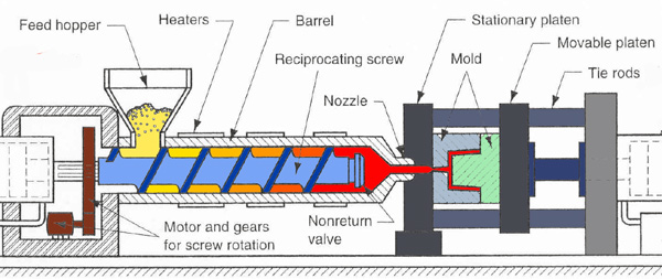
A molding according to the function of each of its parts can be divided into four sections 1. Introductory part of the plastic nozzle into the cavity cavity 2. penunjuang system (support system) 3. demolding system 4. heat transfer system

Mold Base Standard Part

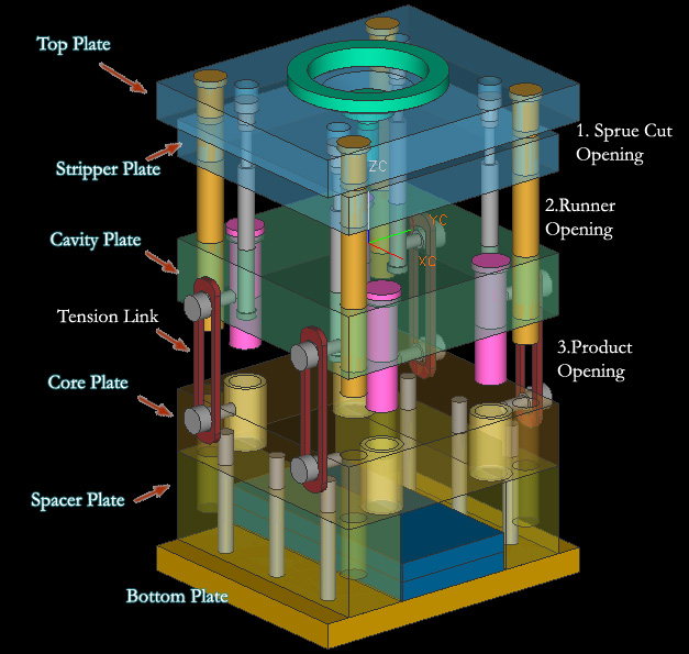
In the manufacture of injection mold, mold base is an integral part, mold maker can make your own mold base or buy a standard mold base, the system of the mold base can be adjusted with the construction standards required, both for the two plate and three plate, stripper plate ejectors, hot runner and mold base for a screw, when the entire standard mold base is not there to meet the new final step is to make a special mold base.

Injection Mould Classification

classification or types of mold injection very depend on what we need to make the plastic parts, because every parts have specific and unique design. when design molds we must see what the influencing factor like geometry, number of cavities, ejection principle, plastic material and shape of part.

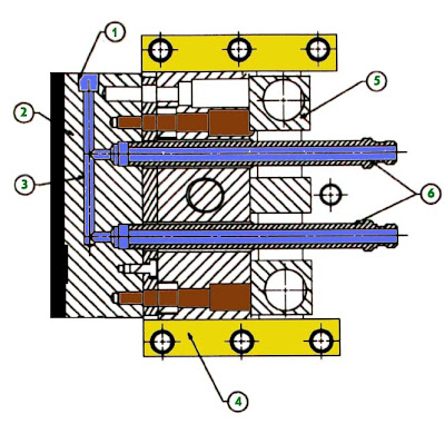
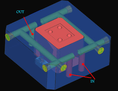
Injection Mold Cooling

This section is the most important part of the overall mold cylcle time, because in one cycle time, the process of heat exchange to spend about 70-80% of the total cycle time, thus setting the optimal heat transfer system will greatly affect the quality and cycle time of a product.

Undercut System : Cam, Angular, Lift Cavity, Loose core

cavity and core, and its derivatives when there are undercut on product, design and construction of a good core cavity and in accordance with the requirement could increase the life of tooling itself, reduce material consumption, reduce dependence on maintenance inserts, and can reduce the cost of making the mold so the mold cost per products also declined.

Wednesday, June 25, 2008

Other Joint Construction Betwen Cooling in cavity and Mold base with O Ring

What is O ring
o-ring is a loop of elastomer with a round (o-shaped) cross-section used as a mechanical seal or gasket. They are designed to be seated in a groove and compressed during assembly between two or more parts, creating a seal at the interface. (wikipedia.com)
O-Rings are torus-shaped (i.e. doughnut-shaped) objects made from elastomeric compounds such as natural or synthetic rubber, and are used to seal mechanical parts against fluid movement (air or liquid). O-Rings perform their sealing action by deforming to take the shape of their cavity, after being oversized to guarantee an predetermined interference fit.( efunda.com)


O ring typically used in one of two seal designs, axial or radial, in mold design to attaching cavity to mold base axial, face type are commonly used then radial type, because axial type is more easy to assembly in mold than radial type.
2D O ring drawing like picture below


Static seals exist where there is no relative motion between the mating surfaces being sealed.


at previous post about basic construction for joining cooling system in cavity and mold base , we can learn how to joint pipe from mold base of mold to cavity site.

various construction can be develop from basic construction, previous post basic construction is fast and cheap construction model, but it isn't good when you in large mold and mass production mold, why? becouse production mold must have endurance until 1000 000 shot.

Picture below shown develop construction of joining cooling pipe


blue color indicate mold base side and yellow color indicate cavity side.
basic rule from those picture are :
1. T is height of O ring
2. part of O ring that will receive pressure form cavity plate. 15-30% from it's height is best. this little pressure give to prevent leak when water flow in cooling system.
3. t2 value is same with t, but t2 is horizontal, becouse O ring always made from elastomer plastic, by little pressure we can add O ring to O ring hole.
4. L is Gap between cooling channel and O ring hole.

O-Ring Design Considerations
1. Proper Squeeze
•Compression expressed as a percentage of the free-state cross-sectional thickness:


•Face Seal: 20-30%
•Static Male/Female: 18-25%
•Reciprocating: 10-20%
•Rotary: 0-10%
2. In static seals, where the O-Ring is not in axial motion in the bore, the recommended maximum compression is approximately 40%.
3. The O-Ring must be compressed by a predetermined amount, and this compression determines the O-Ring cross-section diameter.
4. The O-Ring inner diameter is typically chosen to be close to the groove's inner diameter; by selecting it to be slightly less than the groove's inner diameter, the O-Ring will stretch and hug the groove.
5. The Groove Width must be larger than the O-Ring cross-section diameter, to accommodate the radial expansion of the O-Ring when it's axially compressed in the gland.
6. stretch,
- Excessive stretch can overstress material, thin cross section, and reduces % squeeze
- % cross section reduction due to stretch about half of the % ID stretch
7. Sharp Corners, make R in cornet to prevent damage during seal installation.
8. Pressure and Clearance Gap.
Most elastomeric seals are designed to operate within ambient pressure to about 1,500 psi. At very high pressures, the seal must have sufficient strength to resist extrusion into the clearance gap. The chart at right illustrates the recommended limits of the combination of clearance gap (diametral), seal hardness, and pressure differential. picture below shown graph between clearance gap and pressure


9. When it is said that an elastomer is good for an application it is meant that some compounds which include that material are acceptable. Not All. For instance, some compounds of EP are good for brake fluid applications, but most are not acceptable.
10. DO NOT use a lubricant composed of the same material as the O-ring. For example, a silicone lubricant should NOT be used with a silicone O-ring.
11. Avoid using graphite-loaded compounds with stainless steel, as they tend to pit the stainless steel surface over time.

useful reference
http://www.rlhudson.com/O-Ring%20Book/designing-static.html
http://www.pspglobal.com/application-limits/04-watery-substances.html
http://en.wikipedia.org/wiki/O-ring
http://www.efunda.com/DesignStandards/oring/design_guidelines.cfm#axial
http://www.marcorubber.com
http://www.allorings.com/gland_static_axial.htm
Sunday, June 22, 2008

Construction of Cavity Cooling and Mold Base Cooling, O ring

here the basic construction of joining cavity cooling and mold base cooling, we can use from simple construction to joint cavity and mold base cooling with one O ring, or we can use more complex construction like using special plate, and various O ring seal type. here is basic construction to joint the cavity cooling and mold base cooling.


both circular type and straight type cooling can be joint use those construction,
those construction use in half circular type of cooling system like picture below


click the image to see more large

simple joint just need one O ring or rubber seal, O ring pocket is preferred make in horizontal face from assembly, becouse it's make assembly and machining process mold more easily,
basic rule and tolerance to prevent leak in O ring are like picture below


at the cross section of cavity and mold base cooling construction, blue color indicate mold base part, and light yellow indicate cavity block, green is indicate hole or pipe of cooling. light black is O ring before penetrate with cavity block.
however is the simplest construction to join cooling cavity and mold base.

Tuesday, June 17, 2008

Straight Type Cooling for Cavity

Basically cavity system cooling can divide into two type
1. straight type
2. Circular type

straight type system, usually have in and out of water pipe in not same side of mold or cavity. look at picture below

although the pipe that cool of insert part doesn't straight, but if inlet and outlet cooling fluid is not in same side we can consider that those type of cooling is straight. red color pipe indicate inlet and blue color pipe indicate outlet.

second picture below is still same with previous but this picture include the cavity block


yellow part at each side is plug to prevent unwanted flow of cooling, pink block at the center is core insert part. with attach to core block using bolt. Block with blue color is core block before inserted to mold base.

Saturday, June 7, 2008

Fill time runner balance on 6 cavity of mold

runner balance is important when we works with more than 1 cavity in mold design, unbalancing runner can cause various like unfill mold (short shot), weld line, air traps, burning and others.

from previous post that talk about design of runner balance in 6 cavity, now let's prove it by simulation of filling time.

Unbalance Flow Definition
Unbalanced flow is plastic completely filling some flow paths in the mold before other flow paths have filled. we can see from result of simulation, if color is same in cavity (for example at the end and gate) that mean it have good flow.

1. Unbalance Runner System


from picture above we can consider that flow of plastic in various cavity doesn't fill in the same time, it can cause flashing, short shots, high cycle time, density differences throughout the part, warpage, air traps and extra weld lines.
flashing will occur in cavity that fill earlier, becouse cavity that fill earlier will continue receive plastic flow until other cavity filled (it depend on injection pressure and cycle time set up).
Short shots happened at cavity number that fill more slowly then others cavity then the pressure and cycle time doesn't enough to fill the last cavity.

2. Balance Runner of 6 cavity
although this runner layout is not the best for 6 cavity layout, it better in fill time than runner layout before. look at the picture below


by changing the layout we can get runner that more balance with previous, from cavity number 1 until 6 the fill time is almost same.

Sunday, June 1, 2008

Runner Balance Layout for 6 cavity of mould

Picture below shown layout model for 6 cavity product, star layout used to connecting 3 cavity, then connected again with straight line. distance between one cavity to another is same

Top view


3D view


becouse flow at nearest sprue is faster than other, although the distance from the branch to gate is same, the flow of plastic will not good, nearest sprue will fill first and not same with another.

Improved runner layout

so we need another layout, below is improved runner layout for 6 product cavity, although is not the best, but it's more improved than first. but disadvantage of this runner layout is consume more material.

Top view


3D view