Injection Mould Construction

A molding according to the function of each of its parts can be divided into four sections 1. Introductory part of the plastic nozzle into the cavity cavity 2. penunjuang system (support system) 3. demolding system 4. heat transfer system

Mold Base Standard Part

In the manufacture of injection mold, mold base is an integral part, mold maker can make your own mold base or buy a standard mold base, the system of the mold base can be adjusted with the construction standards required, both for the two plate and three plate, stripper plate ejectors, hot runner and mold base for a screw, when the entire standard mold base is not there to meet the new final step is to make a special mold base.

Injection Mould Classification

classification or types of mold injection very depend on what we need to make the plastic parts, because every parts have specific and unique design. when design molds we must see what the influencing factor like geometry, number of cavities, ejection principle, plastic material and shape of part.

Injection Mold Cooling

This section is the most important part of the overall mold cylcle time, because in one cycle time, the process of heat exchange to spend about 70-80% of the total cycle time, thus setting the optimal heat transfer system will greatly affect the quality and cycle time of a product.

Undercut System : Cam, Angular, Lift Cavity, Loose core

cavity and core, and its derivatives when there are undercut on product, design and construction of a good core cavity and in accordance with the requirement could increase the life of tooling itself, reduce material consumption, reduce dependence on maintenance inserts, and can reduce the cost of making the mold so the mold cost per products also declined.

Tuesday, April 8, 2008

Film Gate Design (flash gate)

Film gate also called flash gate is very thin compare to another gate, this thin gate like film which have parallel runner before the gate, this type of gate used for straight edges. picture below shown film gate with main parts.


in generally this gate used in thin and flat requirement, like flat mobile phone cap, ipod cap and others. but sometimes this gate is not likely going to have a flat flow front, the make flow material more stable and flat, make temperature molds more higher than usual, but cycle time will also higher.

here is film gate from top view


Dimension
recommended dimension is approximately 0.2 mm to 0.6 mm in thick, the land area (parallel runner) is also be kept small approximately 0.6 mm - 1 mm depend the large and weight of product.

Other Design
picture below shown other design of film gate, with more reliable and easy in process.

look the different model of film gate, and different design of parallel runner.
picture below shown simulation of plastic flow from those design

and the last picture shown time that needed to cooling the melt plastic in mold


from the picture above we can choose the right place to make cooling pipe, the red color marks mean need more time to cool the product.

Sunday, March 30, 2008

Tab gate design in Mold

general construction of tab can see at picture below


basically melted material is fed to this gate from a separate primary gate (after runner), the function of the gate typically is employed for flat and thin parts to reduce the shear stress in the cavity, Tab gate able to used in various material plastic such us ABS, PS, acrylic, PP, PVC, Polycarbonate. SAN and other which has relatively low fluidity. at this type of gate, the high shear stress generated around the gate that trimmed after molded. this gate sometimes also called the collision gate.

Function in Product and General Rule
The thickness of tab gate should be the same as the part wall, yo can also make more thin, but when designed parts for cosmetic parts if preferred that the thickness is same with the product thickness.
rule number two is, make the gate as center as possible in the product side, but you must consider the product size and shape.
basically minimum tab width is about 6,5 mm and the tab thickness minimum is 75 % from the thickness product


for more picture and drawing view,please look at picture below

(Top View of Tab Gate)


(Front view of Tab Gate)


(Side View of Tab Gate)

each picture is able to enlarge by clicking the picture.


Friday, March 7, 2008

side gate, edge dimension design

edge gate is the simplest type of gate and is used wherever the product can or must be gated from parting line. it's designed commonly for injection machine attended by operator, because the product must separated from the runner system by hand with the aid of side cutter.

Dimension
Picture below shown ideal configuration and practical gate, suggested dimension for general application of edge or side gate are


Runner width and Height for side gate or edge gate is preferred that height is about 0,7-0,8 from width of runner. the width of runner very depending on product size and weight, it from 3 mm until 7 mm in width ( product mass until 200 gram in maximum).
Gate width and height is about W=3h,with W is width and h is height (look at Herbert Rees, Mold Engineering, pg 159) but this rule can't applied for all part or product form, specially for thick product that have large in width such us panel and cover, when design the dimension of gate take the rule that height of gate is must about 75 % from the parts thickness, Suggested take 0,6 until 0, 7 from parts thickness, but specially for elastomer material take more large about 80-90 % from parts thickness.
T is gate width, for product mass until 200 gr, suggested take 1 until 5 mm in width , for the very large product some times have width until 12 mm.
C is Land of gate from runner, the length is should be no more than 1,5 mm. also preferred make taper before gate land, in that picture taper are change with R in both side, make R, taper or not is depend on side gate size and form.


Picture 1.A

Picture 1.B

both those picture shown edge gate or side gate with different design, application, parting line, taper and R system. taper from bottom runner to gate land have various dimension, the taper in picture 1A is enough large, about 30-45 degree, in picture 1B taper is about 10-20 degree.

beside those type of side gate, they are still various type of side gate or edge gate, will upload in other post.

Side gate, edge gate design

as we know Gate In injection molding, is the channel through which the molten resin flows from the runner into the cavity. Generally, it is small and solidifies first. The restricted opening through which the plastic enters the mold cavity.

Standard Gate
this type of gate have various name, the common name are standard gate, edge gate and side gate, this is the most typical gate in molds, which is applied to almost all types of plastics. look at picture below, it's single side gate from sprue until gate and product (click the picture to enlarge)


how about the parting line?

the are about 3 methods that we can choose when design parting line,
1. core side process,this type of parting line only core side that's must be machined , picture below shown side gate design with flat parting line in core side process.
this type parting line is useful applied in product without taper in side of product, but when product have taper in side (like picture below) it will undercut and need slider to form the side of product.

2. cavity side process, this type of gate design parting line is one method to hide the marks of gate after injection process. at this type runner channel machined in cavity side, then a little gate machined at core side. this type of gate parting line is more good and more cheap than number one when product have taper like picture below.

3. cavity and core side parting line, this type parting line for gate and runner is not common to use, when use this type parting line runner and gate, you must use cylindrical type of runner of semi cylindrical type of runner.

Saturday, February 23, 2008

Direct Gate or Sprue Gate

What is Gate ?
The entrance through which molten plastic flows into the cavity of the mold from the runner. This is where the flow or melting of molten plastic is controlled by control type of gate or gate dimension. It is positioned at the thickest area of a part.
other function of gate is the gate makes it easier for the runner, which will be unnecessary after molding, to be separated from the part.is recommended to consider gating options early in part design.

Direct Gate
direct gate or sprue gate we can define as connecting directly end sprue to the molding and used as a gate,
this type of gate is commonly used for single cavity molds, where sprue feeds the material to cavity molds directly rapidly with minimum pressure drop.

this type of gate is applied to molding of boxes or cups like bathtub, plastic bucket, and others, particularly large sized products. like at the picture above, shown cups product with direct gate before cutting.

Dimensions and Construction

from picture below we can concluded that direct gate is very easy to design,

from picture above the construction of direct gate is one parts with the product, after injection process, the sprue will cut manually.
parting line between cavity and core can directly placed at top surface of product or more lower from top surface product, it very depending of product shape and characteristics.
starting sprue diameter is controlled by nozzle of injection

- then, make sure the diameter of sprue orifices must be larger than nozzle exit diameter, choose from 1-2 mm or about 1/32 inch.
- give taper at the sprue from orifice diameter to product about 1-3 degree, it is will made the product demolded from cavity side more easy.
- in general the diameter of the gate much greater than the thickness of the product.

Advantages
- Low cost of design.
- The injection pressure was reduced due to direct cavity filling.
- Simple way to design gate and runner system.
- easy design and maintenance.

Disadvantages
some disadvantage of direct sprue are:
- since excessive stress is left easily around the gate, cracking often starts around the gate.
- when using non standard sprue tapers, will more expensive with little gain.
- gate mark left on part surface after runner of sprue trimmed of.
- This gate type can only produce one part per shot.
- The gate has to be cut manually by a cutter.
- Not applicable in little size product.

Monday, February 11, 2008

Basic Functions of Mold Base Parts

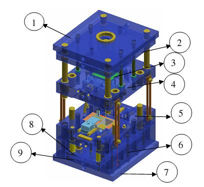
A mold plate is any plate required to built a complete mold, in all plate use for molds have the main requirements, they are :
1. Good corrosion resistant
2. Good Machinability.
3. Easy to clean
3. Good heat transfer.
4. Homogeneity of steel.
5. Easy ability.
6. Low Cost.

at picture below you can see 3 plate mold base type with closed position, basically 3 plate type and 2 plate type has some main plate, see explanation about mold construction type to understand more,


explanation below based on number at those picture
1. Fixed Clamping Plate or Top Plate
Holds The fixed side of the mold to attached at the fixed platen of the injection machine. at this plate will attach locating ring, eye bolt, and sprue bush.
2. Runner Stripper Plate
this plate only used in 3 plate molds type, the function is to cut resin from nozzle in top of sprue bush, and pull the runner by runner locking pin.
3. Fixed Mold Plate or Cavity plate.
use to hold cavity side of product, leader pin, support pin, Puller bolts, and Angular pin when slider attached.
4. Movable Cavity Plate or Cavity plate
it used to attach core side of product, return pin, leader bush and slider core if needed.
5. Back up Plate or Support plate
used to support cavity plate, attach the hole for return pin's spring, and cooling channel when in cavity plate can not make it.
6. Spacer Block
Mounted between the movable clamping plate (bottom plate) and the movable cavity plate to give space and allow the ejector plate to move when ejecting the
part. the required length of spacer block depend on ejector stroke that needed to eject product.
7.Ejector retainer plate
to hold the ejector, Z pin, shoulder bolts,and give space to ejector leader pin and support pillar.
8. Ejector Plate
Pushes the ejector pins and return pins, connected with ejector rods.
9. Movable Clamping Plate or Bottom plate
Holds The movable side of the mold like spacer block, support plate, cavity plate and ejector mechanism to the movable platen of the injection machine.


and look at picture below, shown 3 plate molds type in opening position, but at picture below, Bottom plate or movable clamping plate is number 7, number 8 is ejector retainer plate, and number 9 is ejector plate.