Injection Mould Construction

A molding according to the function of each of its parts can be divided into four sections 1. Introductory part of the plastic nozzle into the cavity cavity 2. penunjuang system (support system) 3. demolding system 4. heat transfer system

Mold Base Standard Part

In the manufacture of injection mold, mold base is an integral part, mold maker can make your own mold base or buy a standard mold base, the system of the mold base can be adjusted with the construction standards required, both for the two plate and three plate, stripper plate ejectors, hot runner and mold base for a screw, when the entire standard mold base is not there to meet the new final step is to make a special mold base.

Injection Mould Classification

classification or types of mold injection very depend on what we need to make the plastic parts, because every parts have specific and unique design. when design molds we must see what the influencing factor like geometry, number of cavities, ejection principle, plastic material and shape of part.

Injection Mold Cooling

This section is the most important part of the overall mold cylcle time, because in one cycle time, the process of heat exchange to spend about 70-80% of the total cycle time, thus setting the optimal heat transfer system will greatly affect the quality and cycle time of a product.

Undercut System : Cam, Angular, Lift Cavity, Loose core

cavity and core, and its derivatives when there are undercut on product, design and construction of a good core cavity and in accordance with the requirement could increase the life of tooling itself, reduce material consumption, reduce dependence on maintenance inserts, and can reduce the cost of making the mold so the mold cost per products also declined.

Saturday, June 26, 2010

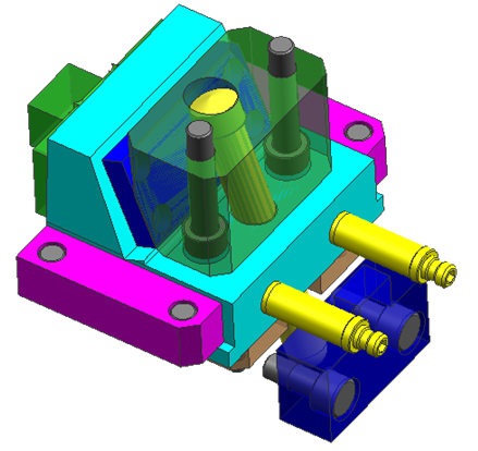
slider construction : cam or angular pin

posts related to construction and part-bagianya slider has been my post, about the cooling on the slider, the basic construction for the slider, the slider and the main part, please see previous post to learn the basic construction and when we should use the slider, This post will discuss about when we need to use of the slider that use angular pin or just cam slider, what advantages and disadvantages of both types of construction such slider. 
ANGULAR PIN
basically, the type of construction of the slider based on how to pull out the core slider is divided into three types, first use the angular pin,using the force of the angular pin at a certain angle, the slider block would be pull out, the second is a cam slider, just use the thrust of the spring and stopper on the slider, and calculating a stroke, cam slider allows you to easily pull the slider core, the third is the use of hydraulic or pneumatic system to pull the slider core, specifically for the third way is needed so that movements of individual controls in accordance when the slider open mold and mold close.picture below shows slider with angular pin system.
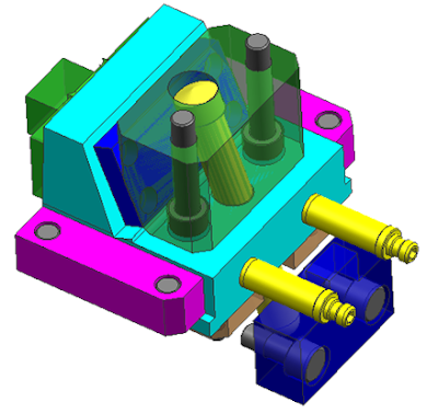


 picture above shown standard complete construction for slider, it's include cooling plug, stopper (blue color), adjustment plate between locking block and slider core(blue), guide rel (pink) etc. angular pin system very common use in slider system, Angular sometimes do not have a round pin, shape the box is also commonly used, actually used the same angle, both will be used by considering the strength, structure, mold, and the available space.
The advantage is the use of angular pins can be used for parts that have undercut short or long, easy to maintain when the angular broken, just enough to change the angular pin. inexpensive in manufacture, and can be used for long-stroke slider to medium, the angular pin length has not touched bottom plate. 


for instance,look at picture above if undercut wide for most of the parts, use the slider two pins with a diameter sufficient, then you will get a strong slider construction and safe.

CAM SLIDER
while the slider does not require angular cam pin, the cam slider there are several types of commonly used, the clamp type,  two angle type, cam units type and one direction cam. because in using the cam to take calculation of a stroke is used, why?? it's to prevent slider core not be separated from the locking block, and the strength of the spring, so that true core slider can move and hit the stopper. cam slider can only be used for minor stroke (0.5 mm-5mm), small undercut, and not too wide undercut form.

a benefit is a cam slider can be used for high cycle time, mold construction, saving space, and easy assembly.

whereas the less than the limited form that can be undercut in the form, was difficult in the manufacture and maintenance. 


Sunday, May 9, 2010

Troubleshooting warpage on injection molds

Warping, Part Distortion is shows up as parts being bowed, warped, bent or twisted beyond the normal specification outlined on the drawing.Warpage occurs when there are variations of internal stresses in the material caused by a variation in shrinkage. Warped parts may not be functional or visually acceptable.

Main Causes
1.Non-uniform cooling
Temperature differences from one side of the mold to the other can lead to layers freezing and shrinking at different times and generating internal stresses.   Temperature differences from one side of the mold to the other (differential cooling).
 2. Inconsistent shrinkage or non uniform stress due excessive orientation of shringkage.Variations in the magnitude of shrinkage in directions parallel and perpendicular to the material orientation direction (orientation effects). 
Process conditions variations such as inconsistent packing and varying mold and melt temperatures;   low pressure, mold temperature of ejection too hot,  Material variations such as property variations, varying moisture content, inconsistent melt and pigmentation; 

Possible Solutions

  • Adjust melt Temperature (increase to relieve molded-in stress, decrease to avoid overpacking). stress, decrease to avoid over packing). stress, decrease to avoid over packing).
  • Check gates for proper location and adequate size.
  • Check mold knockout mechanism for proper design and operation.
  • Equalize/balance mold temperature of both halves.
  • Increase injection-hold.
  • Increase mold cooling time.
  • Perhaps one of the easiest things to alter is the temperature of the coolant. It may be useful to run two additional Cool analyses with the coolant inlet temperatures at say plus and minus 5°C with respect to the original inlet temperature used
  • Relocate gates on or as near as possible to thick sections.
  • Try increasing or decreasing injection pressure.
  • Use thinner wall sections with ribs. Thicken only those wall sections that require extra material for structural stability and that cannot be strengthened using another method.   
  • Change the part geometry. Add features such as stiffening ribs to the design. Change the part design to avoid thick sections and reduce the thickness of any features that intersect with the main surface.  

Wednesday, March 24, 2010

Troubleshooting weld lines and meld lines on injection molds

In manufacturing, the Weld line or Knit line or Meld line is the line where two flow fronts meet when there is the inability of two or more flow fronts to "knit" together, or "weld", during the molding process. These lines occurs usually around holes or obstructions and cause locally weak areas in the molded part.

A weld or meld line is a weakness or visible flaw created when two or more flow paths meet during the filling process. Weld lines can be caused by material flowing around holes or inserts in the part, multiple injection gates or variable wall thickness where hesitation or "race tracking" can occur. If the different flow fronts have cooled before meeting, they don't interfuse well and can cause a weakness in the molded part. A line, notch and/or color change can appear.

What Caused Weld or Melt Line?
A meld line occurs when two moving melt fronts converge and flow parallel to each other. Weld and meld lines are generally caused by holes or inserts in the part, multiple gates, variable wall thickness or hesitation and race track effects.

explanation from http://www.imtechdesign.com/ give brief reason why and when weld line, and melt line will occurs.

a meeting angle, smaller than 135º produces a weld line; greater than 135º, a meld line. Note that the weld line surface mark disappears when the meeting angle reaches 120º to 150º. Normally, weld lines are considered to be of lower quality than meld lines, since relatively less molecular diffusion occurs across a weld line after it is formed. However, there is always an exception to the rule and some materials by nature tend to exhibit more visible weld lines irrespective of the angle. In addition many fillers and additives also highlight weld & meld lines. Glass fibres and metallic pigments are good examples.

Weld lines, melt lines or Knit lines could be caused by different causes:

- Low temperature of molding machine barrel
- Inadequate back pressure
- Injection pressure or injection speed is too low
- Low mold temperature
- Small injection gates and/or runners
- Improper location of injection gate
- Excessive gate land length
- Improper flow rate of injected materials
- Inconsistent process cycle

Weld Line and Physical Properties
A study of the effect that weld lines and orientation have on physical properties of molded parts was undertaken to establish general guidelines for use in part design. an experiment by dupont show that between polymer orientation, Weld Lines. And tensile Strength have Relationship, see graph below.


These results show the importance of gate location and the need for the product
designer to coordinate his efforts with the tool builder. The gate should be located
both to avoid weld lines in high stress areas and to take full advantage of glass fiber reinforcement. Techniques the designer might use to reduce stress level at a weld line include increasing the wall thickness or adding ribs.

Solution
- This can be done by changing the polymer injection location or altering wall thicknesses to set up a different fill time.
- increasing mold temperature, melt temperature, injection rate and pressure.
- Increased mold venting or addition of flow tabs also can help turn a bad weld into
a good weld
- Change the gate positions.
- Change the part thickness.
- Optimize runner system design. Reduce runner dimensions and maintain the same flow rate to use shear heating to increase the melt temperature at the flow front
- Instead, it often helps to increase the injection velocity, decrease the fill time, and increase the shear rate, which can lower the viscosity of the polymer during fill and thereby allow for better chain entanglement and better packing. Increasing pack or hold pressure also helps, as well as having longer pack and hold times. Increasing pack or hold pressure helps to eliminate low-pressure conditions at the weld line. Another tactic to promote more chain entangling at the weld line is to raise the mold temperature 10° C (20° F).

Wednesday, March 3, 2010

Troubleshooting short shot problems on injection mold

The term "short shot" or "short mold" is used to refer to a phenomenon where plastic being injection molded does not reach certain portions of the inside of the die before solidifying. or it means that not enough resin has flowed into the mold to fill it adequately. The main causes for short shot are the mold condition or flowability problems with the resin. The problem is alleviated when a greater volume of resin flows more easily.
To ensure the finished part is of good quality, the part must also be adequately packed with plastic. Therefore the question to ask is not only, ""Will the part fill?"" but also, ""Can a good quality part be made?""


Some of the typical factors affecting this type of problem are as follows:
- Fluidity and viscosity characteristics of the plastic
- mold design (Flow restrictions. Due to channels freezing or inadequate runner design. gate design, bushing construction for ribs and bosses, the presence of venting, .)
- Hesitation and long or complex flow paths.
- Inadequate venting. Back pressure due to unvented air traps can cause a short shot.
- Molding machine performance (Including an empty hopper, blocked feed throat, or a worn non-return (check) valve that causes loss of pressure or volume leakage.)


picture above i copy from UMgabs.com, those check point is very important for troubleshooting short shot problems

Solution
- Eliminate air traps. If air traps do exist, they should be positioned in areas that can be easily vented or ejection pins added so that air can be removed.
- if Resin flows too slowly, Increase temperature in the cylinder. Increase injection speed. If no change in the filling time is noticed after setting of a high injection rate, there is a possibility that the performance of the molding machine is insufficient or that there is excessive pressure loss in the sprues, runners, and gates
- check resin viscosity, Increase the mold temperature.This will decrease the viscosity of the melt, making it easier for the plastic to flow through the part.
- Increase ram speed. This can cause greater shear heating, which decreases the viscosity of the melt, making it easier for the plastic to flow through the part.
- Increase the sectional area of the gate, sprue and runner, and shorten the length. Make the sprue, runner and gate surfaces more slippery.
- Change the gate position, increase the thickness of the mold cavity, modify design to improve flow.
- Change the part geometry. Balance flow paths so they fill in an equal time and an equal pressure. You may need to thicken thin sections, or reduce the complexity of a flow path.
- Use a different material. Select a less viscous material (higher melt flow rate). By choosing a material with a higher melt flow rate, less injection pressure will be required to fill the part.

Friday, February 19, 2010

Stripper Ejector Construction (step by step mold design) part 8 : add return pin

In ejector system, return pin is important, i was post about ejector system, include the function of each part, see it at this link, previous post is adding ejector pin and ejector guide bush in the mold, now next step is adding return pin, when we use mold standard or mold base blank, return pin always include in those mold base blank, if you have the catalog, return pin symbol is always RP, with dimension from X direction and Y direction, see picture below, yellow pin is return pin.


picture below is standard mold base, i get from Lun Kee mold base standard we can show dimension of mold base standard 150 mm x 150 mm with flange 200 mm, return pin diameter 12 mm, with the position 57 in Y direction from 0,0. and 24 in X direction, see the green line at picture below


add the return pin between ejector plate, and ejector stripper plate, the height of return pin same with surface of core plate. make hole in Ej. plate and core plate. like picture below


Spring for Return Pin
this spring will help move back ejector plate and ejector stripper plate after ejecting process, by calculate load of ejector system we can choose the best spring for return pin, too hard spring will difficult to assembly, but too weak spring will give some problem in ejecting process, this spring also help to prevent ejector stuck after ejecting process. see the construction like picture below
some mold designer prefer make hole of spring until half of core plate. which one do you use it depend on load calculation of spring.


Next step are add ejector rod and support pillar
To prevent large deflection in center of cavity plate, we must add support pillar as much as we can, arrange it so the deflection of cavity mold when plastic injecting is minimum, deflection can make gap between cavity plate and core plate, so flashing maybe appear, maximum allowable deflection depend on material, but generally it about 20-30 micron.
In this case I put 4 support pillar symmetrically

To move ejector system, we must add ejector rods, in little mold generally use only 1 pcs of ejector rods until 80 ton still save use only 1 pcs. but if your construction more than 100 ton or mold base size more than 400 mm x 400 mm use more than one pcs of ejector rods.
picture below shown 1 pcs construction of ejector rods.

Saturday, January 30, 2010

Stripper Ejector Construction (step by step mold design) part 7

Ejector Guide Pin and Bush
in this part, we will design ejector guide pin, EGP bush, bolts for stripper plate and bottom plate. first learn ejector system and part at link below

3D ejector drawing

hope you can understand ejector system and ejector guide pin (EGP) function, Ejector guide pin located between ejector plate and ejector stripper plate, to fit the ejector pin, we can add bolt at the bottom of EGP, and clamp it in bottom plate of mold


Bolt for spacer block
To make position of spacer block fit between backing support plate or core plate and bottom plate, add bolts from bottom plate to spacer block, see picture below for more detail. In each spacer block, add 2 pcs of bolts, the other function is when disassembling process spacer block and bottom plate became one part, it make dissembling easier


Ejector Puller Bolts
to push the stripper plate when ejecting proses begin, we need connector from ejector plate to stripper plate at core,in this case, i use ejector puller bolts, you also can use other standard part,just make sure that you can connect ejector plate to stripper plate at core side. see picture below for detail construction.